Vertical guardrail reinforcing and mounting structure

An installation structure and vertical technology, applied in the direction of ladder-like structures, railings, railing posts, etc., can solve the problems of the limit of welding firmness at the end, achieve low cost, increase horizontal force capacity, and increase bottom force value Effect

Pending Publication Date: 2021-12-03
TUS DESIGN GRP CO LTD +1
View PDF9 Cites 0 Cited by
  • Summary
  • Abstract
  • Description
  • Claims
  • Application Information

AI Technical Summary

Problems solved by technology

Even if it is changed to stainless steel, due to the limitations of the rectangular pipe profile itself, the firmness of the end welding also has a certain limit

Method used


Image

  • Vertical guardrail reinforcing and mounting structure
  • Vertical guardrail reinforcing and mounting structure
  • Vertical guardrail reinforcing and mounting structure

Examples


Embodiment Construction

[0027] The above solution will be further described below in conjunction with specific embodiments. It should be understood that these examples are used to illustrate the present invention and not to limit the scope of the present invention. The implementation conditions used in the examples can be further adjusted according to the conditions of specific manufacturers, and the implementation conditions not indicated are usually the conditions in routine experiments.

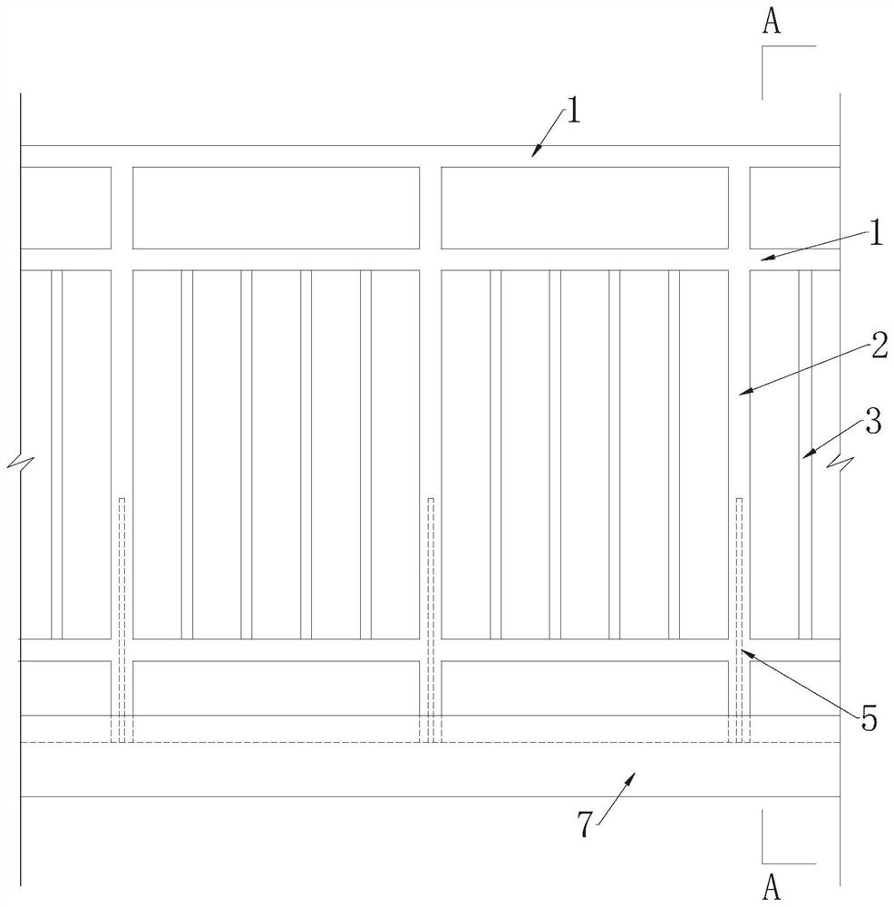
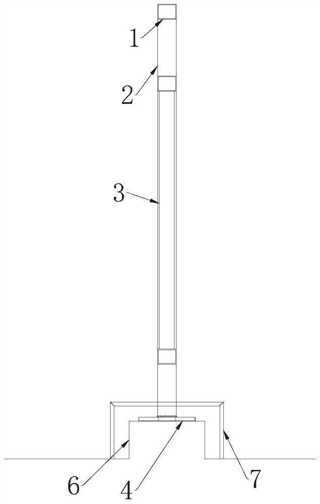
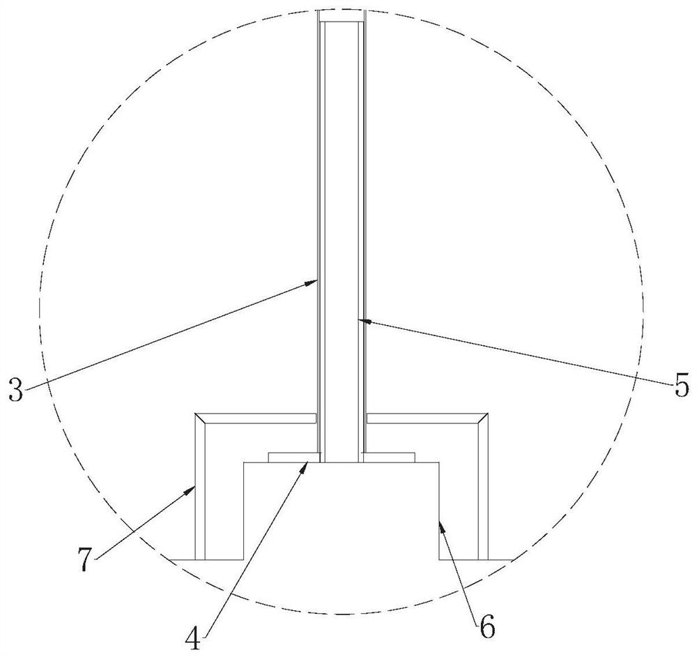
[0028] see Figure 1-3 , is a structural schematic diagram of an embodiment of the present invention, providing a vertical guardrail reinforcement installation structure, including a plurality of transverse force-bearing members 1 arranged at intervals from top to bottom, and a plurality of transverse force-bearing members 1 connected and arranged at intervals Vertical force-bearing members 2 and a plurality of connecting pieces 3 arranged between adjacent vertical force-bearing members 2 .

[0029] In this exa...


PUM


Abstract

The invention discloses a vertical guardrail reinforcing and mounting structure which comprises a plurality of transverse stress components arranged at intervals from top to bottom, a plurality of vertical stress components connected with the transverse stress components and arranged at intervals, and a plurality of connecting pieces arranged between the adjacent vertical stress components. The upper end and the lower end of the connecting piece are connected with the adjacent transverse stress components respectively, the lower end of the vertical stress component is fixed to the rear embedded part, a reinforcing component is arranged in the vertical stress component, the rear embedded part is provided with a penetrating opening for the reinforcing component to stretch in, and the lower portion of the reinforcing component is fixedly connected with the rear embedded part. According to the vertical guardrail reinforcing and mounting structure, the safety performance of the guardrail can be improved, and the cost is low.

Description

technical field [0001] The invention relates to the technical field of guardrails, in particular to a reinforcement installation structure for a vertical guardrail. Background technique [0002] In the design process of the school guardrail, limited to the consideration of specifications and safety, the vertical (mainly rectangular tube) guardrail is the main form, and the form of this guardrail is basically the welding form of the lower end of the rectangular tube and the rear buried plate. The rectangular pipe was also changed from galvanized pipe to stainless steel in the early stage to avoid potential safety hazards caused by late end corrosion. Even if it is changed to stainless steel, due to the limitations of the profile itself of the rectangular pipe, the firmness of the end welding also has a certain limit. Contents of the invention [0003] Based on the above problems, the purpose of the present invention is to provide a vertical guardrail reinforcement installa...

Claims


Application Information

Patent Timeline
Patent Type & Authority Applications(China)
IPC IPC(8): E04F11/18
CPCE04F11/181E04F11/1817E04F11/1842
Inventor 蔡爽徐剑锋
Owner TUS DESIGN GRP CO LTD
Why Eureka
Try Eureka