
Contact network annular steel pipe column weld joint grinding equipment

A steel pipe column and catenary technology, which is applied in the direction of grinding/polishing equipment, metal processing equipment, grinding machines, etc., can solve the problems of high labor intensity of operators, high technical level of operators, low production efficiency, etc., and achieve grinding and polishing The effect of good quality, simple structure design and low labor intensity

Pending Publication Date: 2021-12-03
CHINA RAILWAY SHENGLE BAODING ELECTRONICS CO LTD +2
View PDF0 Cites 0 Cited by
  • Summary
  • Abstract
  • Description
  • Claims
  • Application Information

AI Technical Summary

Problems solved by technology

This kind of welding seam processing method firstly grinds, then polishes, the production efficiency is low, the operator is labor-intensive, and safety is not easy to guarantee. Manual positioning requires high technical level of the operator, and t

Method used


Image

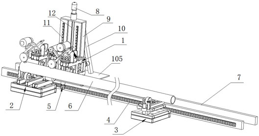
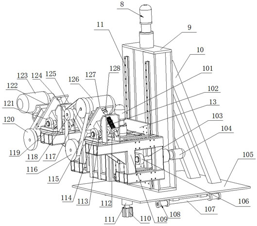
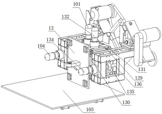
  • Contact network annular steel pipe column weld joint grinding equipment
  • Contact network annular steel pipe column weld joint grinding equipment
  • Contact network annular steel pipe column weld joint grinding equipment

Examples


Example Embodiment

[0021] The present invention is further described in the drawings and in conjunction with the specific embodiments below.

[0022] like Figure 1 to 5 , The present embodiment includes two tracks 7, the host 1 and the linkage comprises a welded steel pipe column 6 can remain in the horizontal position the large end of the roller means 2 and the small end of the steel column support mechanism roller mechanism 3.

[0023] The large end support roller mechanism comprises a base 2 Ⅰ201, two large end rollers 202 and 204, the motor and gear plate 203 Ⅰ205. Two roller large end is formed between the steel support column 202 and the large end 204. Both ends of the major side rollers 202 and 204, respectively, by the output shaft of the motor Ⅰ205 206 is rotatably secured to the base Ⅰ201, fixed to the base via a coupling Ⅰ201 bearing housing and wherein a large end of the roller shaft 204 rigid connection. Gear 203 is fixed to the rear end of the base plate located at the large end Ⅰ201 s...


PUM


Abstract

The invention discloses contact network annular steel pipe column weld joint grinding equipment. The contact network annular steel pipe column weld joint grinding equipment comprises two rails, a main machine linkage mechanism and a steel pipe column supporting mechanism comprising a large-end carrier roller mechanism and a small-end carrier roller mechanism which can enable a steel pipe column weld joint to be kept at the horizontal position; the main machine linkage mechanism comprises a base, a left-right walking mechanism, a vertical rack, two vertical linear guide rails I, a sliding block I, a power mechanism driving the sliding block I to ascend and descend along the vertical linear guide rails I, a base III fixed to the side face of the sliding block I, a grinding mechanism and a polishing mechanism; the grinding mechanism and the polishing mechanism can be mounted on the base III in an up-and-down fine adjustment and front-and-back fine adjustment manner; and a machine base I is fixed on a base IV in an inclination angle adjustable mode, a base V is fixed on the base III in a height fine-adjustment mode and in a front-back mode, and a machine base II is fixed on the base V in an inclination angle adjustable mode. According to the contact network annular steel pipe column weld joint grinding equipment, grinding and polishing are synchronously carried out, welding seams are automatically aligned, the production efficiency is high, the labor intensity of operators is small, safety is achieved, and the grinding and polishing quality is good.

Description

technical field [0001] The invention belongs to the field of manufacture of catenary ring steel pipe columns, and relates to a welding seam grinding equipment of catenary ring steel tube columns. Background technique [0002] At present, the steel plate is generally used as the material of the ring-shaped steel pipe column of the electrified railway catenary in my country, and the general processing and forming process of the main steel pipe is: bending machine bending → closing machine closing → automatic submerged arc welding machine welding → weld seam grinding, etc. After the welding is completed, there are one or two long longitudinal welds in the steel pipe column body, and there is a small amount of welding spatter around the welds. The longitudinal welds and their surroundings need to be ground and polished. The grinding method at this stage generally uses a trolley grinder to grind, and after the basic pass, use a trolley polisher to polish and repair the weld seam....

Claims


Application Information

Patent Timeline
IPC IPC(8): B24B21/00B24B21/18B24B21/20B24B29/04B24B27/00B24B55/00B24B41/02B24B41/06
CPCB24B21/002B24B21/008B24B21/18B24B21/20B24B29/04B24B27/0076B24B55/00B24B41/02B24B41/067
Inventor 胡会良徐伟超张帆崔浩官义军许德强曹素兴梁岩商顺超方和王涛牛江辉刘旭映李建东周永强采云飞王鹏王孟高耀宗田红凡郭锦川郎唯博段玉博刘涛李晓东
Owner CHINA RAILWAY SHENGLE BAODING ELECTRONICS CO LTD
Learn More