
Precise stamping forming equipment for arc-shaped bottom cover of boiler

A technology of precision stamping and forming equipment, applied in the direction of pushing out equipment, metal processing equipment, feeding devices, etc., can solve the problems of low precision and complicated operation, and achieve the effect of easy collection and processing, and convenient follow-up operations

Pending Publication Date: 2021-12-03
彭宜伟
View PDF0 Cites 0 Cited by
  • Summary
  • Abstract
  • Description
  • Claims
  • Application Information

AI Technical Summary

Problems solved by technology

[0005] In order to overcome the shortcomings of complex operation and low precision, the technical problem to be solved is: provide a simplified and automatic operation process, which is convenient for users to collect and process, and improves the precision of stamping forming for boiler arc bottom cover precision stamping forming equipment

Method used


Image

  • Precise stamping forming equipment for arc-shaped bottom cover of boiler
  • Precise stamping forming equipment for arc-shaped bottom cover of boiler
  • Precise stamping forming equipment for arc-shaped bottom cover of boiler

Examples


Embodiment 1

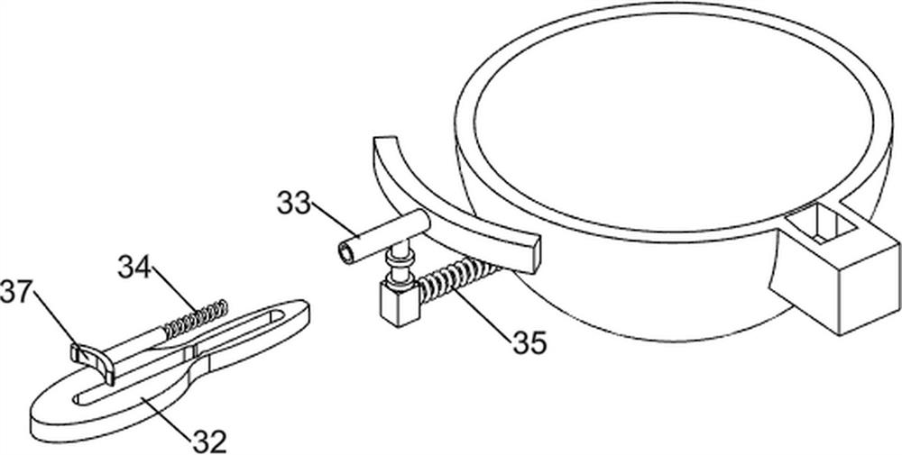
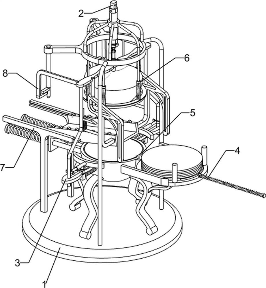
[0068] A precision stamping and forming equipment for a boiler arc bottom cover, such as figure 1 As shown, it includes a base 1 , a punching mechanism 2 and a fastening mechanism 3 , the punching mechanism 2 is connected to the upper side of the base 1 , and a plurality of fastening mechanisms 3 are connected to the upper side of the base 1 .

[0069]When the equipment needs to be practical, the user can place the raw material plate on the fastening mechanism 3, start the punching mechanism 2, and the telescopic rod of the punching mechanism 2 is extended, so that the punching mechanism 2 moves downward to achieve the For the purpose of punching the plate, the punching mechanism 2 moves downward to drive the fastening mechanism 3 to move downward. When the fastening mechanism 3 is in contact with each other, the fastening mechanism 3 is pushed to slide inward. At this time, the fastening mechanism 3 is compressed. Clamp the raw material plate to achieve the purpose of clampin...

Embodiment 2

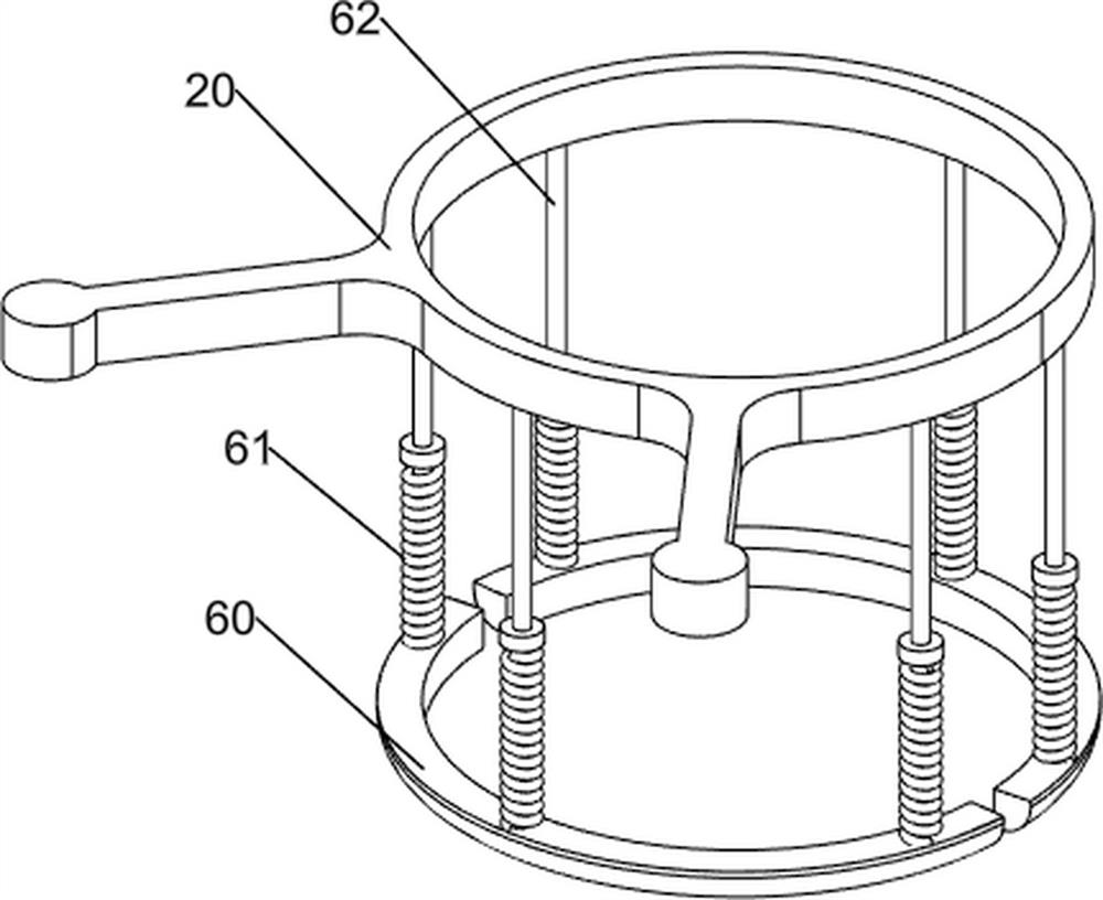
[0071] On the basis of Example 1, such as figure 2 As shown, the punching mechanism 2 includes a second support frame 20, a cylinder 21 and a gravity block 22, the upper side of the base 1 is connected with the second support frame 20, the inner side of the second support frame 20 is connected with a cylinder 21, and the cylinder 21 passes through the first Two support frames 20, a gravity block 22 is connected on the expansion rod of the cylinder 21, and a pressure bar 23 is connected on the gravity block 22.

[0072] When the device needs to be practical, the user can place the raw material plate on the fastening mechanism 3, start the cylinder 21, the stretch rod of the cylinder 21 drives the gravity block 22 to move downward, and the gravity block 22 moves downward to drive the pressure rod 23 Moving down to achieve the purpose of stamping the raw material plate, the downward movement of the pressure rod 23 drives the fastening mechanism 3 to move downward, and the follow...


PUM


Abstract

The invention relates to stamping forming equipment, in particular to precise stamping forming equipment for an arc-shaped bottom cover of a boiler. According to the precise stamping forming equipment for the arc-shaped bottom cover of the boiler, the operation process is simplified and automated, collection and treatment are convenient for a user, and the precision of stamping forming is improved. The precise stamping forming equipment for the arc-shaped bottom cover of the boiler comprises a base, a stamping forming mechanism and fastening mechanisms; the stamping forming mechanism is connected to the top side of the base; and the multiple fastening mechanisms are connected to the top side of the base. Through cooperation of a second supporting frame, an air cylinder, a gravity block and a pressure rod, the aim of stamping a raw material plate is achieved.

Description

technical field [0001] The invention relates to a stamping forming equipment, in particular to a precision stamping forming equipment for a boiler arc bottom cover. Background technique [0002] In industrial production, parts of various materials and shapes are required, and the production of these parts requires stamping processing. Stamping processing uses the power of conventional or special stamping equipment to make the sheet metal directly in the mold. Deformation force and deformation, so as to obtain the production technology of product parts with certain shape, size and performance. Stamping processing can be divided into precision stamping and ordinary stamping. [0003] Precision stamping is a material processing method developed on the basis of ordinary stamping technology. It is through improving the guiding precision, reducing the gap between the punch and the concave die, increasing the reverse pressure and v-ring blank holder, etc., resulting in strong Unde...

Claims


Application Information

Patent Timeline
IPC IPC(8): B21D22/02B21D43/00B21D45/04B21D43/02B21D51/44
CPCB21D22/02B21D43/003B21D45/04B21D43/02B21D51/446
Inventor 彭宜伟
Owner 彭宜伟
Learn More