Optimization system and method for receiving ground noise in optical fiber transmission link
An optical fiber transmission and link technology, used in transmission systems, electromagnetic wave transmission systems, electromagnetic receivers, etc., can solve problems such as inability to optimize, and achieve the effects of low signal flatness, guaranteed communication quality, and high signal-to-noise ratio.
- Summary
- Abstract
- Description
- Claims
- Application Information
AI Technical Summary
Problems solved by technology
Method used
Image
Examples
Embodiment 1
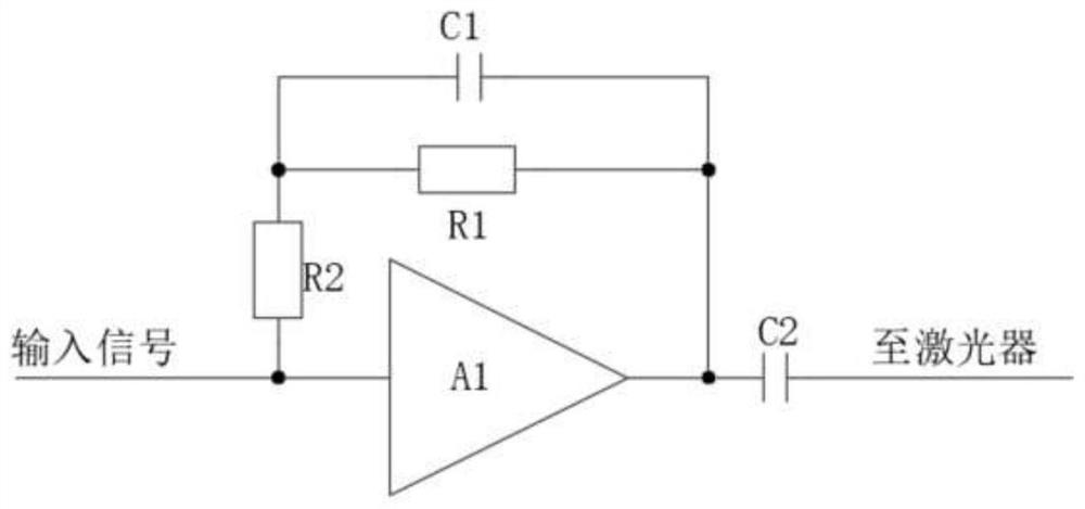
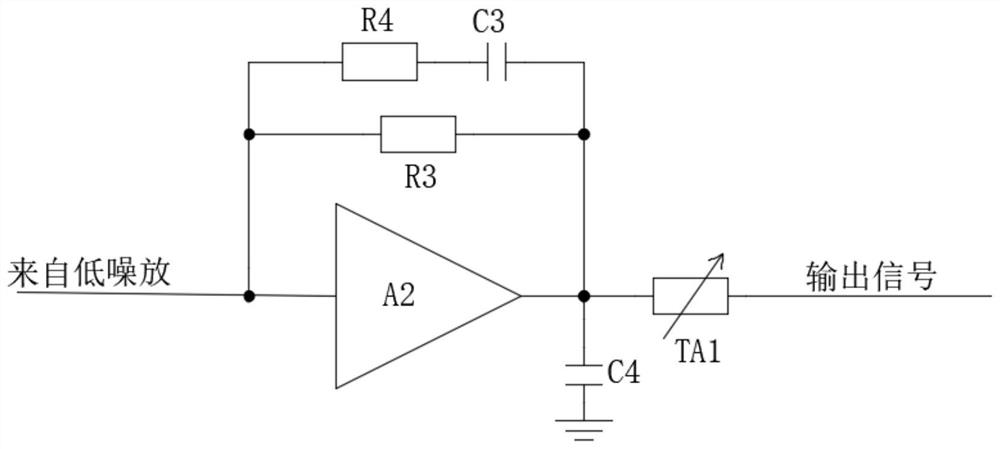
[0038]In order to solve the problem in the prior art that it is impossible to optimize the low-noise reception in the high-frequency band of the optical fiber transmission link, this implementation provides an optimization system for receiving the noise floor in the optical fiber transmission link. The system includes a transmitting end and a receiving end, and the transmitting end It includes a gain compensation circuit for compensating the gain of the high frequency band of the signal, so that the gain of the low frequency band is low and the gain of the high band is high. The receiving end includes a gain compression circuit for compressing the gain of the high band of the signal, even if the gain of the low frequency band is high The gain of the high-frequency band is linearly reduced, so that the output noise floor of the high-frequency band is lower than that of the original optical fiber link, and the low noise of the whole frequency band shows a flat trend, which ensures...
Embodiment 2
[0050] This implementation is to solve the problem in the prior art that it is impossible to optimize the low-noise reception in the high-frequency band of the optical fiber transmission link, and provides an optimization system for the reception noise floor in the optical fiber transmission link, which has the same inventive concept as Embodiment 1. The system includes a transmitting end and a receiving end. The transmitting end includes a gain compensation circuit for compensating the gain of the high frequency band of the signal. Gain compression circuit, even if the gain in the low frequency band is high and the gain in the high frequency band is linearly reduced, the output noise floor in the high frequency band is lower than that of the original optical fiber link, and the low noise in the whole frequency band shows a flat trend, which ensures the gain flatness and makes the system signal flatness Small, high signal-to-noise ratio, ensuring communication quality.
[0051...
Embodiment 3
[0054] In order to solve the problem in the prior art that the low-noise reception in the high-frequency band of the optical fiber transmission link cannot be optimized, this implementation provides a method for optimizing the reception noise floor in the optical fiber transmission link, which has the same inventive concept as Embodiment 1. Methods include:
[0055] A gain compensation circuit is set at the transmitting end and a gain compression circuit is set at the receiving end. The gain compensation circuit compensates the gain of the high frequency band of the signal, and the gain compression circuit compresses the gain of the high frequency band of the signal, so that the output noise floor of the high frequency band is relatively low. The original optical fiber link drops, which in turn makes the signal flatness of the system small and the signal-to-noise ratio high, ensuring the communication quality.
[0056] Further, the gain compensation circuit is specifically the...
PUM
 Abstract
Description
Claims
Application Information
 - Generate Ideas
- Intellectual Property
- Life Sciences
- Materials
- Tech Scout
- Unparalleled Data Quality
- Higher Quality Content
- 60% Fewer Hallucinations
Browse by: Latest US Patents, China's latest patents, Technical Efficacy Thesaurus, Application Domain, Technology Topic, Popular Technical Reports.
© 2025 PatSnap. All rights reserved.Legal|Privacy policy|Modern Slavery Act Transparency Statement|Sitemap|About US| Contact US: help@patsnap.com


