Multi-frequency antenna combination structure and method for mining radio wave perspective
A technology of radio wave perspective and multi-frequency antenna, applied in the direction of antenna support/installation device, electrical components, transmission system, etc., can solve the problem of poor consistency of transmission power, achieve consistency, realize automatic tuning, and solve the problem of transmission power The effect of poor consistency
- Summary
- Abstract
- Description
- Claims
- Application Information
AI Technical Summary
Problems solved by technology
Method used
Image

Examples
Embodiment 1
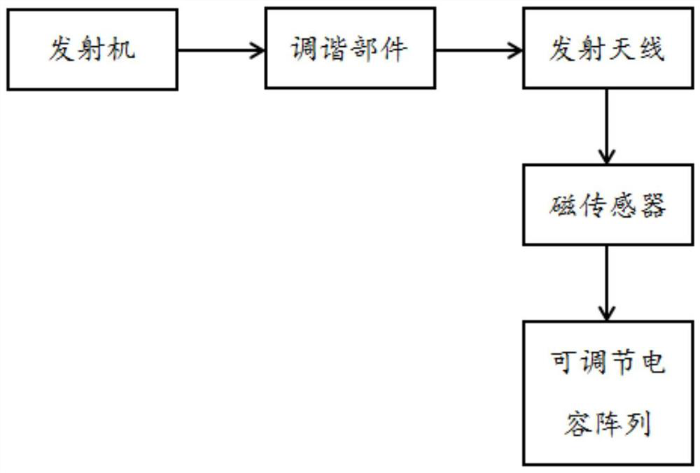
[0035] The embodiment is basically as attached figure 1 As shown, it includes: a transmitter, the output terminal of the transmitter is connected with a tuning component, the output terminal of the transmitter is connected with the input terminal of the tuning component through the first interface, and the tuning component is used to convert the low voltage output by the transmitter into a high voltage The tuning component is connected to a transmitting antenna, the output end of the tuning component is connected to the transmitting antenna through the second interface, and the transmitting antenna is used to transmit the tuned high voltage;
[0036] It also includes: a magnetic sensor, the magnetic sensor is connected to the transmitting antenna, and the magnetic sensor is used to collect the current value on the transmitting antenna; the magnetic sensor is connected to a microprocessor, and the microprocessor is connected to an adjustable capacitor array; the microprocessor i...
Embodiment 2
[0045] The only difference from Embodiment 1 is that the coupling transformer includes a magnetic ring and an enameled wire, and the enameled wire is tightly wound on both sides of the magnetic ring, one side of the magnetic ring is tightly wound by the enameled wire to form the primary coil of the coupling transformer, and the other side of the magnetic ring is tightly wound by the enameled wire The secondary coil of the coupling transformer is formed; the coupling transformer, the compensation capacitor, the adjustable capacitor, the first interface and the second interface are encapsulated as a whole through silica gel, which simplifies the structure and saves space.
Embodiment 3
[0047] The only difference from Embodiment 2 is that after the magnetic sensor collects the current value on the transmitting antenna, the current value on the transmitting antenna collected by the magnetic sensor is corrected. Generally speaking, magnetic sensors convert the magnetic property changes of sensitive components caused by external factors such as magnetic field, current, temperature, light, stress and strain into electrical signals to detect corresponding physical quantities, such as current, position, direction and other physical parameters. Due to the presence of magnetic materials inside the magnetic sensor, degaussing may occur under the action of external factors, such as external magnetic field, heating, high temperature, impact, so that the direction of the magnetic moment of each magnetic domain in the magnetic material will become inconsistent, resulting in magnetic weakening or Disappear, and then cause the current value on the transmitting antenna collec...
PUM
 Abstract
Description
Claims
Application Information
 - R&D
- Intellectual Property
- Life Sciences
- Materials
- Tech Scout
- Unparalleled Data Quality
- Higher Quality Content
- 60% Fewer Hallucinations
Browse by: Latest US Patents, China's latest patents, Technical Efficacy Thesaurus, Application Domain, Technology Topic, Popular Technical Reports.
© 2025 PatSnap. All rights reserved.Legal|Privacy policy|Modern Slavery Act Transparency Statement|Sitemap|About US| Contact US: help@patsnap.com