A driving end pin lamp tube with heat insulation function and its assembly process
A driving end and pin insertion technology, which is applied in the field of driving end pin insertion lamps and its assembly process, can solve the problems of difficult internal components stable assembly, LED lamp bead temperature rise, inconvenient disassembly and maintenance, etc., to increase light diffusion performance, increased thermal insulation performance, the effect of good thermal insulation
- Summary
- Abstract
- Description
- Claims
- Application Information
AI Technical Summary
Problems solved by technology
Method used
Image
Examples
Embodiment 1
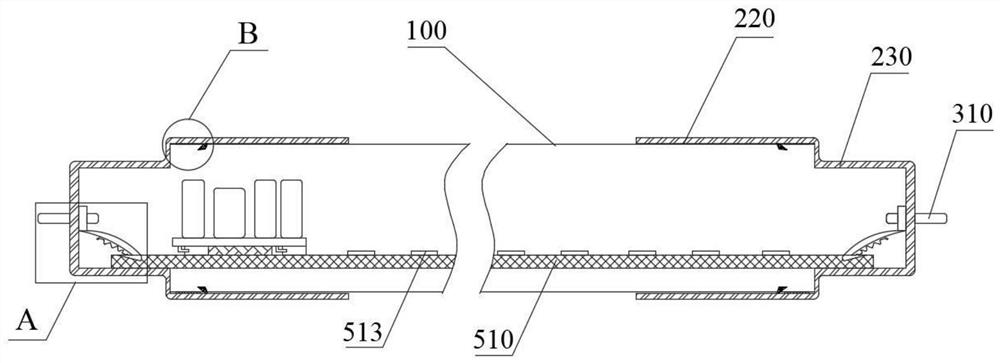
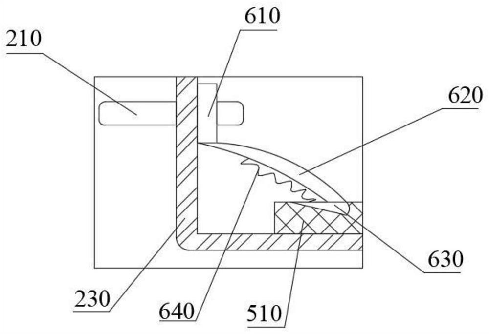
[0035] like figure 1 , Figure 5As shown in the figure, the present embodiment provides a driving-end pin lamp with a heat insulation function, including a lamp cover 100 and a first lamp cap 200 and a second lamp cap 300 assembled on both sides of the lamp cover 100. The lamp cover 100 The inner cavity of the assembly area with the first lamp cap 200 and the second lamp cap 300 is provided with a power supply assembly 400 and a flexible lighting assembly 500, one end of the first lamp cap 200 is provided with a first contact pin 210, and one end of the second lamp cap 300 is provided with a second Contact pin 310; the flexible lighting assembly 500 includes a flexible circuit board 510, the two sides of the flexible circuit board 510 conduct current with the first contact pin 210 and the second contact pin 310 through the elastic snap-on conduction mechanism 600, and the bottom of the power supply assembly 400 A heat insulating adhesive layer 520 is provided between the flex...
Embodiment 2
[0045] like Figure 1-4 , Image 6 As shown, in the driving end pin lamp tube with heat insulation function of this embodiment, the lamp tube cover 100 is a detachable assembly structure, including a first tube body 110 and a second tube body 120 which are symmetrically arranged. The first tube body 110 Both ends of the first pipe body 110 and the second pipe body 120 are semicircular, and the two ends of the first pipe body 110 are horizontally provided with clamping grooves 111 . The cross-sectional shape of the second pipe body 120 is L-shaped; the inner wall of the second pipe body 120 is provided with a step 122 for placing the flexible circuit board 510, and the inner walls of the first pipe body 110 and the second pipe body 120 are distributed in an annular array with a plurality of snap grooves 123; A plurality of concave rings 124 are provided on the periphery of the first tube body 110 and the second tube body 120 near the ends.
[0046] The lamp tube cover 100 can...
Embodiment 3
[0048] like Figure 1-4 , Figure 6-7 As shown, the first lamp cap 200 and the second lamp cap 300 have the same structure, and both include a plug portion 220 and an end portion 230 integrally formed with the plug portion 220. The plug portion 220 is close to the inner wall of the end portion 230. A plurality of clamping blocks 221 that cooperate with the clamping grooves 123 are distributed, and the inner wall of the plug-in portion 220 between the clamping blocks 221 and the end portion 230 is provided with a plurality of wear-resistant convex rings 222 that cooperate with the concave ring 124; The end portion 230 is provided with a through hole 231 through which the first power inlet pin 411 and the second power inlet pin 412 pass through.
[0049] During assembly, the snap-fit grooves 123 on the inner walls of the first tube body 110 and the second tube body 120 are snap-fitted with the snap-fit blocks 221 on the inner wall of the plug-in portion 220 , and the wear-r...
PUM
 Abstract
Description
Claims
Application Information
 - R&D
- Intellectual Property
- Life Sciences
- Materials
- Tech Scout
- Unparalleled Data Quality
- Higher Quality Content
- 60% Fewer Hallucinations
Browse by: Latest US Patents, China's latest patents, Technical Efficacy Thesaurus, Application Domain, Technology Topic, Popular Technical Reports.
© 2025 PatSnap. All rights reserved.Legal|Privacy policy|Modern Slavery Act Transparency Statement|Sitemap|About US| Contact US: help@patsnap.com


