Control method and control device of flyback converter

A technology of a flyback converter and a control method, which is applied in the output power conversion device, control/regulation system, conversion of DC power input to DC power output, etc., can solve problems such as the loss of the flyback converter, and reduce the loss. , control is simple, avoid common effects

Inactive Publication Date: 2021-11-26
MORNSUN GUANGZHOU SCI & TECH
View PDF2 Cites 1 Cited by
  • Summary
  • Abstract
  • Description
  • Claims
  • Application Information

AI Technical Summary

Problems solved by technology

[0008] In view of this, the purpose of the present invention is to provide a control method and control device for a flyback converter, which mainly solves the loss problem of the existing flyback converter working under high frequency and high voltage conditions. At the same time, the invention is applicable to output current Smaller low-power occasions, and can save costs

Method used


Image

  • Control method and control device of flyback converter
  • Control method and control device of flyback converter
  • Control method and control device of flyback converter

Examples


no. 1 example

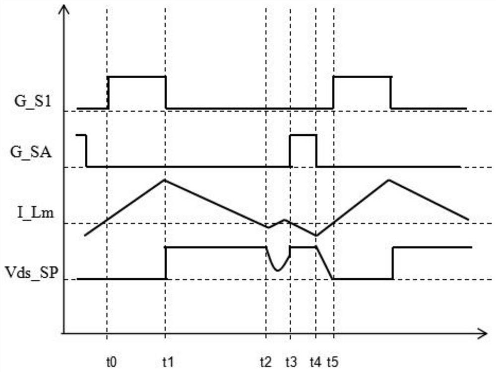
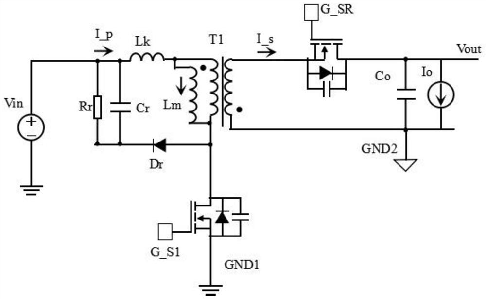
[0084] Fig. 3 (a) is a circuit schematic diagram of a flying transducer according to a first embodiment of the present invention, and the flyback transformer of Fig. 3 (a) includes a primary lateral primary power switch tube M1, a secondary side switching stream unit 230, a transformer T1, clamp circuit 204, feedback circuit 243, output capacitance CO, control device of the present invention, including primary side controller 240, isolation circuit 241, secondary side controller 242, and feedback circuit 243; primary side controller 240 According to the input voltage detection signal Vin_S obtained by the input voltage, generate a control signal SW to control the opening and switching of the primary side main power switch M1, and also determine the operation mode according to the input voltage detection signal Vin_S to generate another original side synchronization signal SR. The isolation circuit 241 outputs the control signal G_SR after the secondary side controller 242 is outpu...

no. 2 example

[0098] Fig. 4 (a) is a circuit schematic diagram of a flyback converter according to a second embodiment of the present invention, and Fig. 4 (a) is different from the first embodiment in the output power detection signal FB by the feedback circuit 243, detecting input voltage And output power to switch the working mode of the anti-storm transform. This embodiment increases the detection output power, and the object is to further control the switching condition of the first mode of operation and the second mode of operation in different situations of the high input voltage to achieve optimization of performance under different loads under high input voltages.

[0099] Fig. 4 (b) is a schematic view showing a switching waveform of a flyback converter according to a second embodiment of the present invention, when the input voltage detecting signal Vin_S is greater than or equal to the first threshold Vth_vin1 and the output power detecting signal FB is greater than or equal to the ...


PUM


Abstract

The invention discloses a control method and control device of a flyback converter. The switching control of a first working mode and a second working mode is carried out through input voltage detection or input voltage detection and output power detection; quasi-resonance switching-on of a primary side main power switch tube and synchronous rectification of a secondary side switch rectification unit are realized under low input voltage, and zero-voltage switching-on of the primary side main power switch tube and synchronous rectification of the secondary side switch rectification unit are realized under high input voltage or above a certain load under the high input voltage. The control method and control device realize simplicity in control and are low in circuit cost and can well balance low cost and high efficiency in a high-frequency application occasion.

Description

Technical field [0001] The present invention relates to the field of switching converters, in particular, it relates to a control method and control apparatus of a flyback converter. Background technique [0002] Flyback converter widely used in low-power switching power supply, with the higher frequency, the development needs of small volume, the proportion of the switching loss of the flyback converter is increased significantly, especially at certain pressure conditions. [0003] Quasi-resonant flyback converter (QRFlyback) can be achieved trough the primary-side main power switch is turned on, the switching loss is reduced, its low cost circuit, a control method is simple, low-power switching power supply is more popular applications Topology. However, in high frequency applications, although the quasi-resonant flyback converter may be implemented valley turned, but in the high voltage input, the switching loss is also growing, it will seriously affect the efficiency of the c...

Claims


Application Information

Patent Timeline
Patent Type & Authority Applications(China)
IPC IPC(8): H02M3/335H02M1/08
CPCH02M3/33592H02M1/08H02M1/083Y02B70/10
Inventor 李健王海洲李樟红
Owner MORNSUN GUANGZHOU SCI & TECH
Why Eureka
Try Eureka