Multi-layer resistance tape equal temperature rise calculation method

A calculation method, the technology of resistance band, applied in the field of temperature rise calculation, can solve the problems of brake resistance device disconnection, overheating of resistance band, cost increase, etc., and achieve the effects of stable resistance value, reduced volume, and reduced material consumption

Active Publication Date: 2021-11-26
XIAN RAILWAY SIGNAL
View PDF4 Cites 0 Cited by
  • Summary
  • Abstract
  • Description
  • Claims
  • Application Information

AI Technical Summary

Problems solved by technology

If the maximum temperature rise of all resistance bands in the braking resistor device is used as the design criterion, there is still a large margin for the temperature rise of the resistance bands close to the fan, resulting in increased costs, and uneven temperature rise will cause resistance bands Local overheating, blown or even ablated, resulting in open circuit or short circuit failure of the braking resistor

Method used


Image

  • Multi-layer resistance tape equal temperature rise calculation method
  • Multi-layer resistance tape equal temperature rise calculation method
  • Multi-layer resistance tape equal temperature rise calculation method

Examples


Embodiment 1

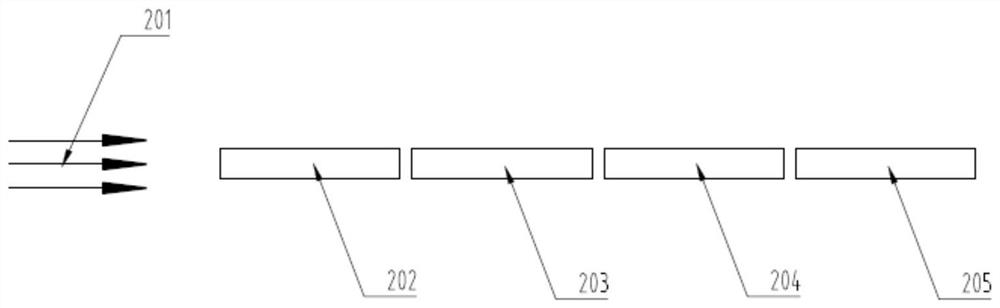
[0048] This embodiment discloses a calculation method for a braking resistor device, the structural diagram of which is shown in figure 2 . In this embodiment, four resistance strips of equal width are arranged in parallel along the flow direction of the cooling air 201: the first resistance strip 202 for the flow, the second resistance strip 203 for the flow, the third resistance strip 204 for the flow, and the resistance strip 204 for the flow. Flow 4th resistance strip 205 . It should be noted that the number of resistance bands in this embodiment is only a braking resistor device scheme using the calculation method of the present invention, and does not restrict the calculation method of the present invention. The number of resistance bands can be determined according to actual engineering needs. Adjustment.

[0049] In this example, the design input includes the total power .

[0050] In order to make the temperature rises of the 4 resistance bands in the present em...

Embodiment 2

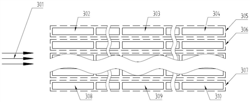
[0080] This embodiment discloses a calculation method for a braking resistor device, the structural diagram of which is shown in figure 2 . In this embodiment, it includes the first row of resistance strips 305 arranged in parallel along the flow direction of the cooling air 301, and the first row of resistance strips 305 includes N equal-width resistance strips: the first row meets the first resistance strip 302 ... the first row 1 row of resistance strips 303 facing the flow and the first row of resistance strips 304 facing the flow; in this embodiment, in addition to the resistance strips 305 of the first row, it also includes the second row arranged perpendicular to the flow direction of the cooling air 301 Row of resistance strips 306... Mth row of resistance strips 307: the Mth row of resistance strips 307 includes N equal-width resistance strips: the Mth row of resistance strips 308 ... the Mth row of resistance strips 308 ... the Mth row of resistance strips of i 309...


PUM


Abstract

The invention relates to a heat dissipation technology of a brake resistor device, in particular to a multi-layer resistance tape equal temperature rise calculation method. The method is characterized by comprising a plurality of resistance tapes with equal width, and the resistance tapes are arranged in parallel along the flowing direction of cooling air; and braking current passes through the resistance belts, heat is generated and convective heat exchange with cooling air is carried out, the heat generated by the resistance belts is taken away, and the temperature rise of the resistance belts is equal under the stable working condition by adjusting the distribution power of the resistance belts. One purpose of the invention is to provide a multi-layer resistance tape equal temperature rise calculation method, which can provide a multi-layer resistance tape structure with equal temperature rise. The equal temperature rise calculation method for the multilayer resistance tape is less in input data and simple in calculation, and compared with a simple qualitative analysis method or a test method, the equal temperature rise calculation method for the multilayer resistance tape enables the calculation process to be quicker and the design result to be more accurate.

Description

technical field [0001] The invention relates to the heat dissipation technology of a braking resistor device, in particular to a method for calculating the temperature rise of a multilayer resistor band. Background technique [0002] The braking resistor device is suitable for diesel locomotives, electric locomotives, light rail locomotives and motor vehicles, etc. When the locomotive brakes, the traction motor changes from the series-excited electric mode to the separately-excited power generation mode. At this time, the kinetic energy of the locomotive is converted into electrical energy, and the generated electrical energy is converted into heat energy through the resistance band of the braking resistor device. The cooling air passing through the resistance will be carried away and dissipated in the atmosphere. At the same time, the armature winding produces a reverse braking force to slow down the wheelset. [0003] When the braking resistor device is working, a large a...

Claims


Application Information

Patent Timeline
Patent Type & Authority Applications(China)
IPC IPC(8): G06F30/20G06F119/08
CPCG06F30/20G06F2119/08
Inventor 武阳吴志东王峰陈超马晨王俭高梅吕俊峰何侃房广禄李忱
Owner XIAN RAILWAY SIGNAL
Why Eureka
Try Eureka