Anesthetic waste gas extraction device for anesthesiology department

A waste gas and department technology, applied in the field of medical devices, can solve the problems of low waste gas treatment efficiency and inconvenient replacement of waste gas treatment materials, and achieve the effects of simple operation, improved waste gas treatment efficiency, and increased absorption area.

Pending Publication Date: 2021-11-26
张如意
View PDF0 Cites 0 Cited by
  • Summary
  • Abstract
  • Description
  • Claims
  • Application Information

AI Technical Summary

Problems solved by technology

[0005] Aiming at the deficiencies in the prior art, the present invention provides an anesthesia waste gas extraction device for anesthesia departments, which is equipped with an anesthesia pump that is started to allow the exhaust gas inside the anesthesia room to enter the inside of the intake pipe through the gas collection hood, and then Enter the interior of the treatment box through the air outlet pipe for exhaust gas treatment. When pumping air, start the motor to rotate the rotating shaft and the rotating rod. Pull the support rod through the connecting rod to swing left and right on the treatment box, and then make the collector on the top of the connecting plate The gas hood swings left and right to increase the exhaust gas absorption area and improve the efficiency of exhaust gas treatment; the filter cyl

Method used


Image

  • Anesthetic waste gas extraction device for anesthesiology department
  • Anesthetic waste gas extraction device for anesthesiology department
  • Anesthetic waste gas extraction device for anesthesiology department

Examples


Embodiment Construction

[0030] The following will clearly and completely describe the technical solutions in the embodiments of the present invention with reference to the accompanying drawings in the embodiments of the present invention. Obviously, the described embodiments are only some, not all, embodiments of the present invention. Based on the embodiments of the present invention, all other embodiments obtained by persons of ordinary skill in the art without making creative efforts belong to the protection scope of the present invention.

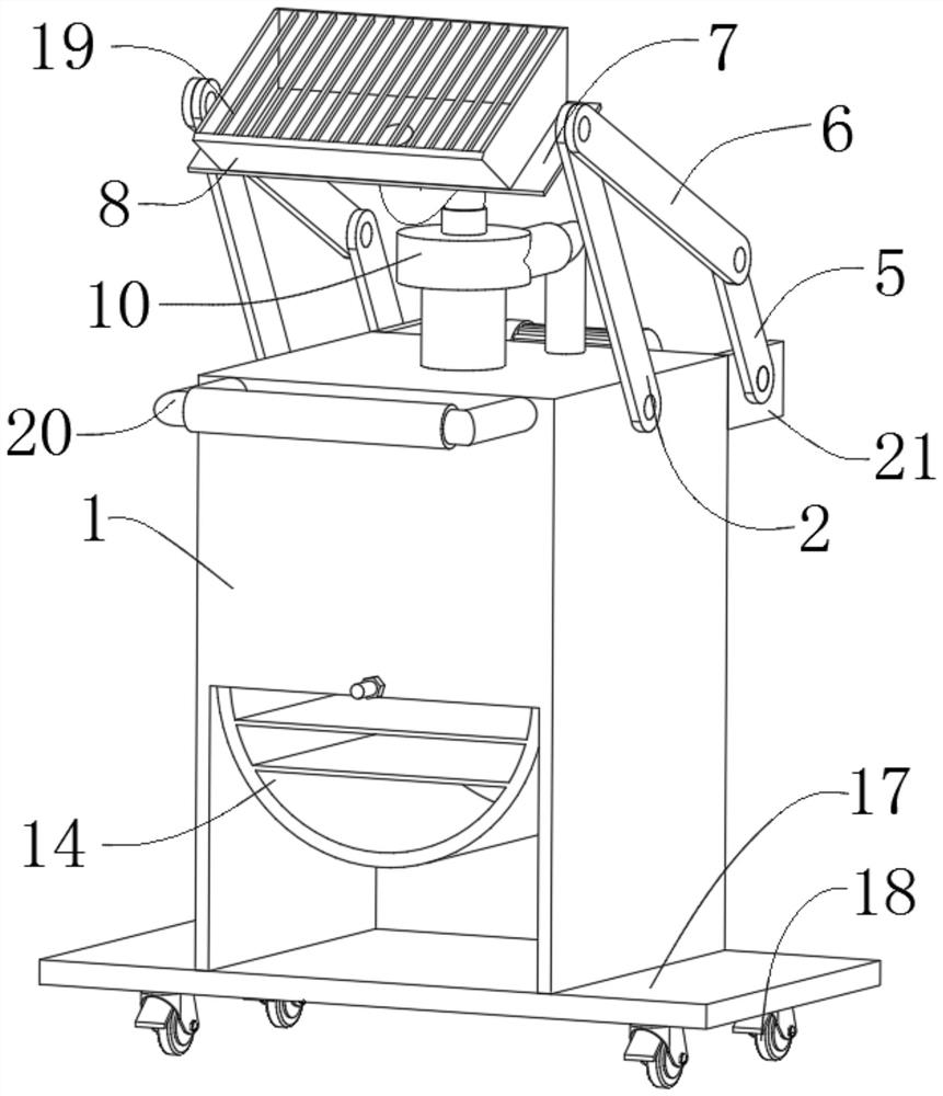
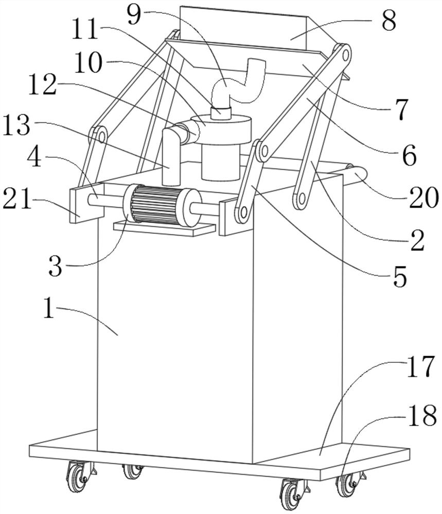
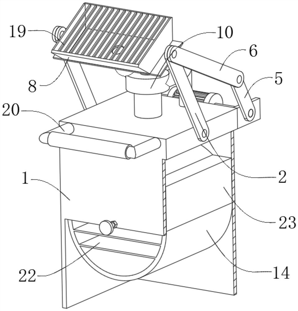
[0031] see Figure 1-4 , an anesthesia waste gas extraction device for an anesthesia department, characterized in that it includes a processing box 1, a support rod 2 is movably connected to one side of the processing box 1, a motor 3 is fixedly connected to one side of the processing box 1, and one of the motors 3 The side is fixedly connected with a rotating shaft 4;

[0032] The outer surface of the rotating shaft 4 is fixedly connected with a rotating rod...


PUM


Abstract

The invention relates to the technical field of medical instruments, and discloses an anesthetic waste gas extraction device for an anesthesiology department. The anesthetic waste gas extraction device for the anesthesiology department comprises a treatment box, one side of the treatment box is movably connected with a supporting rod, one side of the treatment box is fixedly connected with a motor, one side of the motor is fixedly connected with a rotating shaft, the outer surface of the rotating shaft is fixedly connected with a rotating rod, one side of the rotating rod is movably connected with a connecting rod, and the connecting rod is movably connected to one side of the supporting rod. The anesthetic waste gas extraction device for the anesthesiology department has the advantages that by arranging a connecting plate, during gas extraction, a gas extraction pump is started, so that waste gas in an anesthesia chamber enters a gas inlet pipe through a gas collection hood and then enters a treatment box through a gas outlet pipe for waste gas treatment; during gas extraction, the motor is started, a rotating shaft rotates, and the rotating rod rotates; the connecting rod pulls the supporting rod to swing left and right on the treatment box, so that the gas collection hood at the top of the connecting plate swings left and right; and therefore, the waste gas absorption area is increased, and the waste gas treatment efficiency is improved.

Description

technical field [0001] The invention relates to the technical field of medical devices, in particular to an anesthesia waste gas extraction device for an anesthesia department. Background technique [0002] Hospital operations will use anesthesia machines to anesthetize patients. During this process, exhaust gas is usually discharged directly into the anesthesia operating room, which not only easily causes secondary inhalation of patients, affects the inhaled dose of anesthetic, but is also easily inhaled by medical staff in the operating room. Affecting the normal work of medical staff, it is easy to cause problems such as dizziness, fatigue, and lack of energy in a short period of time. An anesthesia waste gas extraction device for anesthesia departments is needed. [0003] However, when the current exhaust gas extraction device is in use, the exhaust gas is usually pumped into the interior of the device through the exhaust port of the exhaust fan for treatment. The effici...

Claims


Application Information

Patent Timeline
IPC IPC(8): B08B15/00B01D46/00B01D53/04F16M11/42
CPCB08B15/00B01D46/0036B01D46/0041B01D53/0407B01D53/0446F16M11/42B01D2253/102B01D2259/40084
Inventor 张如意舒蕤高天勤
Owner 张如意
Why Eureka
Try Eureka