Peritoneal fluid treatment device

A liquid treatment and peritoneal dialysis technology, used in peritoneal dialysis, dialysis systems, suction devices, etc., can solve the problems of residual peritoneal dialysis fluid, operator cross-infection, low separation efficiency, etc., to achieve fast separation speed and avoid peritoneal dialysis fluid. Splashing, the effect of improving separation efficiency

Active Publication Date: 2022-05-31
PEOPLES HOSPITAL OF DEYANG CITY
View PDF0 Cites 0 Cited by
  • Summary
  • Abstract
  • Description
  • Claims
  • Application Information

AI Technical Summary

Problems solved by technology

[0002] In the process of daily medical work, the peritoneal dialysis solution is basically cut directly with scissors to break the collection bag, and then pour the peritoneal dialysis fluid into the toilet or the peritoneal dialysis fluid treatment pool. During this process, the peritoneal dialysis fluid is easily splashed to the ground It will not only cause environmental pollution but also easily cause cross-infection to the operator, so now there is a treatment device for treating peritoneal dialysis fluid, which can reduce the operator’s direct contact with peritoneal dialysis fluid Thereby reducing the possibility of peritoneal dialysis fluid causing cross-infection to the operator and causing pollution to the environment; but when the existing device separates the peritoneal dialysis fluid from the collection bag, the separation of the peritoneal dialysis fluid in the collection bag is not sufficient, and the collection bag will Residual peritoneal dialysis fluid, the peritoneal dialysis fluid collected in the collector is less than the actual peritoneal dialysis fluid collected in the collection bag, which will affect the analysis results of the peritoneal dialysis fluid; at the same time, the existing processing device cannot continuously perform peritoneal dialysis Separation of liquid and collection bag, low separation efficiency

Method used


Image

  • Peritoneal fluid treatment device
  • Peritoneal fluid treatment device
  • Peritoneal fluid treatment device

Examples


Embodiment 1

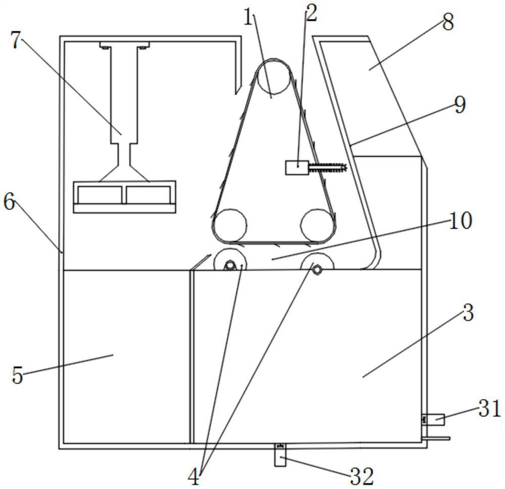
[0049] The waste bag collection cavity 5 is arranged at the output end of the extrusion part 10. In this embodiment, the collection bag is squeezed

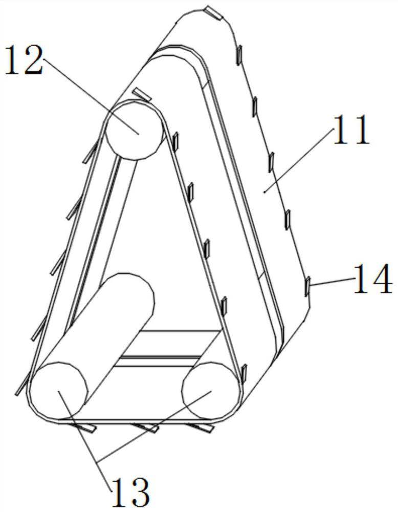
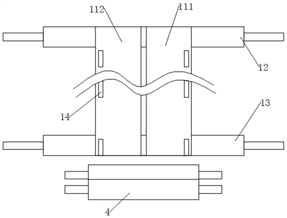
[0052] The belt a111 and the belt b112 are provided with a number of pressing pieces 14 for clamping the collection bag, and a number of the

[0054] The axes of the driven shaft 13 and the bag press roller 4 are both in the same vertical plane and parallel to each other; this embodiment

[0055] Each of the driven shafts 13 corresponds to one of the bag-pressing rollers 4, and from the input end of the extrusion portion 10 to the

[0061] The intelligent terminal 8 also includes a control module for controlling the external drive device 15, the cutter 2 and the electronically controlled valve.

[0064] The monitoring window 33 is provided with several color contrast blocks 34 for contrasting with the color of the peritoneal dialysis fluid. This implementation

Embodiment 2


PUM


Abstract

The invention discloses a device for treating peritoneal dialysis fluid, which belongs to the technical field of medical devices. device, the cutting direction of the cutter is perpendicular to the conveying direction of the collection bag conveying mechanism; The extrusion part of the bag; the waste bag collection cavity is arranged at the output end of the extrusion part. The residual peritoneal fluid in the collection bag is completely expelled by the squeeze part on the collection bag, and the peritoneal fluid is fully separated from the collection bag, thereby reducing the impact of the separation process on the analysis results of the peritoneal fluid; The collection bag delivery mechanism is a closed-loop conveyor belt structure, so it can realize the continuous delivery of the collection bag, and then can realize the continuous separation of the collection bag and the peritoneal dialysis fluid, thereby improving the separation efficiency of the device.

Description

A peritoneal dialysis fluid treatment device technical field [0001] The present invention relates to the technical field of medical devices, in particular to a peritoneal dialysis fluid processing device. Background technique In the process of daily medical work, for the treatment of peritoneal dialysate, basically all directly cut and collect with scissors bag, and then dump the peritoneal dialysis solution into the toilet or the peritoneal dialysis solution treatment tank. Splashing on the operator's hand will not only cause environmental pollution but also easily cause cross-infection to the operator, so there is now a A treatment device for treating peritoneal dialysis fluid, which can reduce the probability of operator's direct contact with peritoneal dialysis fluid and reduce peritoneal dialysis fluid Potential for cross-contamination of operators and contamination of the environment; however, existing devices are separating peritoneal dialysis fluid from colle...

Claims


Application Information

Patent Timeline
Patent Type & Authority Patents(China)
IPC IPC(8): A61M1/28
CPCA61M1/28A61M1/287
Inventor 谢赛徐兴英唐利群
Owner PEOPLES HOSPITAL OF DEYANG CITY
Why Eureka
Try Eureka