
Control method and control device of conversion circuit

A technology of conversion circuit and control method, applied in output power conversion device, control/regulation system, conversion of DC power input to DC power output, etc. and other problems, to prevent sudden changes in current or voltage, prevent output voltage overvoltage, and ensure stability.

Active Publication Date: 2021-11-23
KEHUA DATA CO LTD +1
View PDF5 Cites 2 Cited by
  • Summary
  • Abstract
  • Description
  • Claims
  • Application Information

AI Technical Summary

Problems solved by technology

[0003] However, in the case of light load or high input voltage, since the minimum duty cycle has been limited to more than 0.5, the output voltage can only be reduced to the minimum value corresponding to the duty cycle of 0.5, which cannot be reduced to meet the control requirements. The voltage value is continuously raised due to uncontrolled, unable to stabilize at the required operating point, which eventually leads to overvoltage of the output voltage

Method used


Image

  • Control method and control device of conversion circuit
  • Control method and control device of conversion circuit
  • Control method and control device of conversion circuit

Examples


Embodiment Construction

[0032] The following will clearly and completely describe the technical solutions in the embodiments of the present invention with reference to the drawings in the embodiments of the present invention. Obviously, the described embodiments are preferred embodiments of the invention and should not be seen as excluding other embodiments. Based on the embodiments of the present invention, all other embodiments obtained by persons of ordinary skill in the art without creative efforts fall within the protection scope of the present invention.

[0033] In the claims, description and above-mentioned drawings of the present invention, unless otherwise clearly defined, the terms "first", "second" or "third" are used to distinguish different objects, not for Describe a specific order.

[0034] In the claims, description and above-mentioned drawings of the present invention, if the terms "comprising", "having" and their variants are used, it is intended to mean "including but not limited...


PUM


Abstract

The invention discloses a control method and a control device for a conversion circuit. The control method comprises the following steps: acquiring an electrical parameter of the conversion circuit and a preset value corresponding to the electrical parameter; obtaining a first control quantity based on the electrical parameter and a preset value; performing proportional adjustment and amplitude limiting processing on the first control quantity to obtain a second control quantity, performing amplitude limiting processing on the first control quantity to obtain a third control quantity, and enabling the second control quantity and / or the third control quantity to linearly change along with the first control quantity; and respectively controlling the step-down module and the step-up module by adopting the second control quantity and the third control quantity. The control device corresponds to the control method. The control method and the control device are suitable for preventing the output voltage of the conversion circuit from being overvoltage, the control complexity is simplified, and the working stability of the circuit is improved.

Description

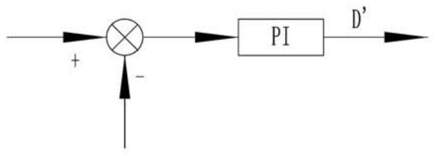
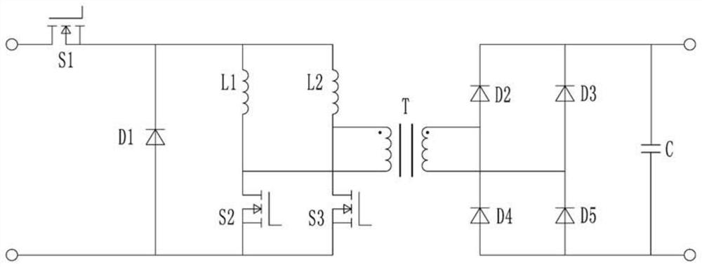
technical field [0001] The invention relates to the technical field of conversion circuit control, in particular to a control method and a control device for a conversion circuit. Background technique [0002] The existing dual-inductance current mode push-pull circuit such as figure 1 As shown, the characteristics of this topology are: in order to provide a freewheeling path for the inductor current, the duty ratios of the switches S1 and S2 need to overlap, so the duty ratios of the switches S1 and S2 are greater than 0.5. Generally speaking, closed-loop control of the input current can be used to make the above-mentioned push-pull circuit work stably. The current closed-loop control loop is as follows: figure 2 As shown, in the case of sufficient load, the push-pull circuit can work stably through the current closed loop. [0003] However, in the case of light load or high input voltage, since the minimum duty cycle has been limited to more than 0.5, the output voltage...

Claims


Application Information

Patent Timeline
IPC IPC(8): H02M3/335
CPCH02M3/33569Y02B70/10
Inventor 陈文佳吴庆彬陈钦鸿罗春李
Owner KEHUA DATA CO LTD
Learn More