Transformer iron core structure and power transformer
A transformer core and power transformer technology, applied in transformer/inductor cooling, transformer/inductor noise damping, transformer/inductor magnetic core, etc., can solve the problems of uncontrollable transformer capacity and large load loss, and achieve Avoid cracking or microscopic cracks, reduce loss, and reduce the effect of voltage power
- Summary
- Abstract
- Description
- Claims
- Application Information
AI Technical Summary
Problems solved by technology
Method used
Image
Examples
Embodiment 1
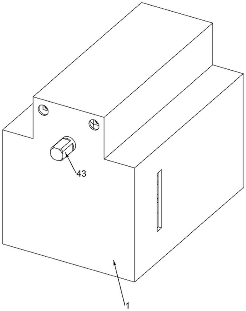
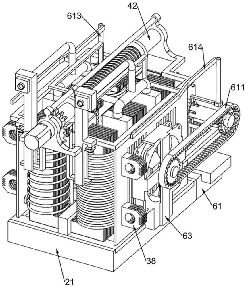
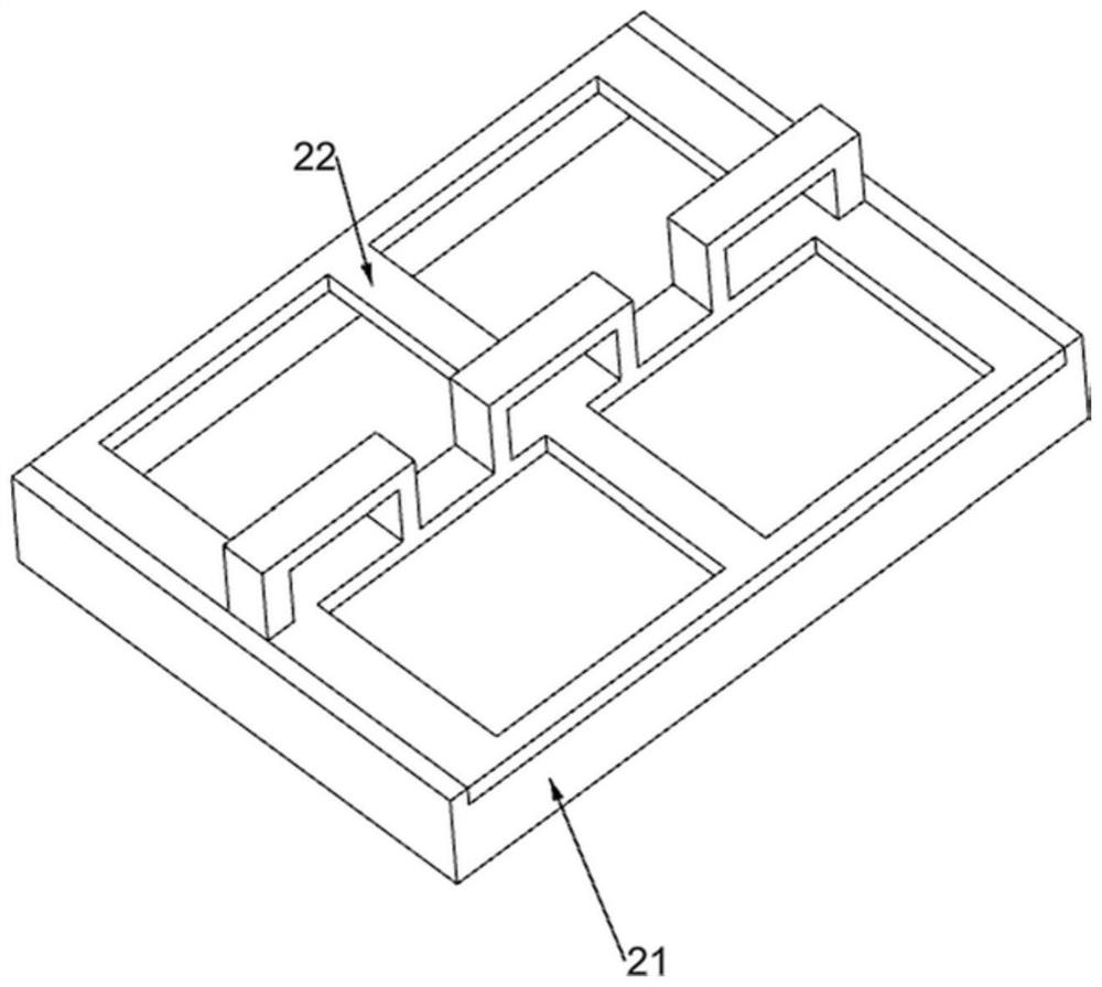
[0042] A transformer core structure and a power transformer, such as figure 1 , figure 2 , image 3 , Figure 4 , Figure 5 , Figure 6 , Figure 7 , Figure 8 , Figure 9 , Figure 10 , Figure 11 , Figure 17 and 18 As shown, it includes a casing 1, a bottom plate chamber 21, a slotted support frame 22, a transformer component 3 and an adjustment component 4. A bottom plate cavity 21 is fixedly installed in the casing 1, and a bottom plate cavity 21 is fixedly installed on the bottom plate cavity 21. There is a slotted support frame 22 on which the pressure transformation component 3 is arranged, and an adjustment component 4 is arranged on the pressure transformation component 3 .
[0043] The transformer component 3 includes a silicon steel chip 31, a main coil 32, a sealing plate 33, a secondary coil 34, a secondary coil 2 35, a secondary coil 3 36, a wiring board 37 and a silicon steel terminal 38. Three stacks of silicon steel chips 31 are arranged in a dis...
Embodiment 2
[0048] On the basis of Example 1, such as Figure 7 , Figure 8 and Figure 9 As shown, an oil injection part 5 is also included. The oil injection part 5 is arranged on the perforated support frame 41. The oil injection part 5 includes a P-shaped slotted frame 51, an electromagnetic valve 52, an oil guide pipe 53, a sector gear 54, L-shaped rack frame 55, first return spring 56, sliding tooth block 57, second return spring 58 and magnetic valve switch 59, two P-type slotted frames 51 are affixed on the described perforated support frame 41, described An electromagnetic valve 52 is arranged above the P-shaped slotted frame 51, and an oil guide pipe 53 is connected to the electromagnetic valve 52. The oil guide pipe 53 communicates with the two sealing partitions 33, and the sector gear 54 is fixedly connected to the lead screw 42. , the P-shaped slotted frame 51 is vertically slidably connected with an L-shaped rack frame 55, and a first return spring 56 is connected between...
Embodiment 3
[0052] On the basis of Example 2, such as Figure 10 , Figure 11 , Figure 12 , Figure 13 , Figure 14 , Figure 15 , Figure 16 and Figure 17As shown, it also includes a variable speed heat dissipation component 6. The variable speed heat dissipation component 6 is arranged on one side of the bottom plate chamber 21. The variable speed heat dissipation component 6 includes a fixed support block 61, a servo motor 62, a fan cover 63, glass fiber reinforced Plastic fan 64, transmission gear 65, slotted sleeve 66, sliding rod 67, first return spring 68, sliding gear 69, second return spring 610, elastic steel belt 611, L-shaped slotted frame 612, belt rod Arc-shaped sliding sleeve 613 and wedge-shaped push rod 614, a fixed support block 61 is fixedly installed on one side of the bottom plate chamber 21, a servo motor 62 is fixedly installed on the fixed support block 61, and the slotted support frame 22 is symmetrical A fan cover 63 is fixedly installed, and the fan cov...
PUM
 Abstract
Description
Claims
Application Information
 - R&D
- Intellectual Property
- Life Sciences
- Materials
- Tech Scout
- Unparalleled Data Quality
- Higher Quality Content
- 60% Fewer Hallucinations
Browse by: Latest US Patents, China's latest patents, Technical Efficacy Thesaurus, Application Domain, Technology Topic, Popular Technical Reports.
© 2025 PatSnap. All rights reserved.Legal|Privacy policy|Modern Slavery Act Transparency Statement|Sitemap|About US| Contact US: help@patsnap.com


