Numerical simulation method for calculating flow field characteristics of closed bypass pipeline system

A technology of numerical simulation and flow field characteristics, applied in the field of pipeline simulation, it can solve problems such as slowing down the convergence speed, and achieve the effect of reducing the amount of meshes, making full use of computing resources, and optimizing the calculation boundary conditions.

Pending Publication Date: 2021-11-23
HARBIN ENG UNIV
View PDF0 Cites 0 Cited by
  • Summary
  • Abstract
  • Description
  • Claims
  • Application Information

AI Technical Summary

Problems solved by technology

while y 十 It is also related to the Re number. The higher the Re number, the higher the y 十 constant, the smaller the actual distance between the wall surface and the first layer of mesh, the smaller the time step that the calculation can take, and the corresponding slowing down of the convergence speed

Method used


Image

  • Numerical simulation method for calculating flow field characteristics of closed bypass pipeline system
  • Numerical simulation method for calculating flow field characteristics of closed bypass pipeline system

Examples


Embodiment Construction

[0022] The present invention is described in more detail below in conjunction with accompanying drawing example:

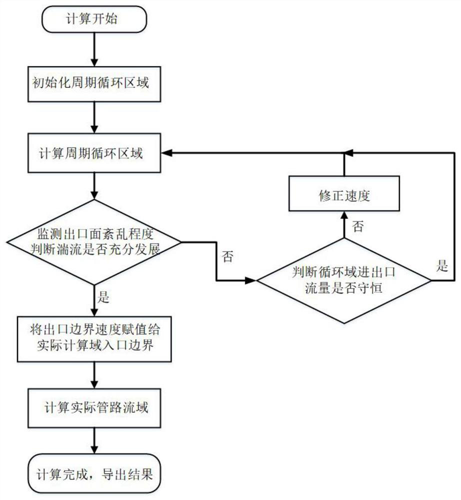
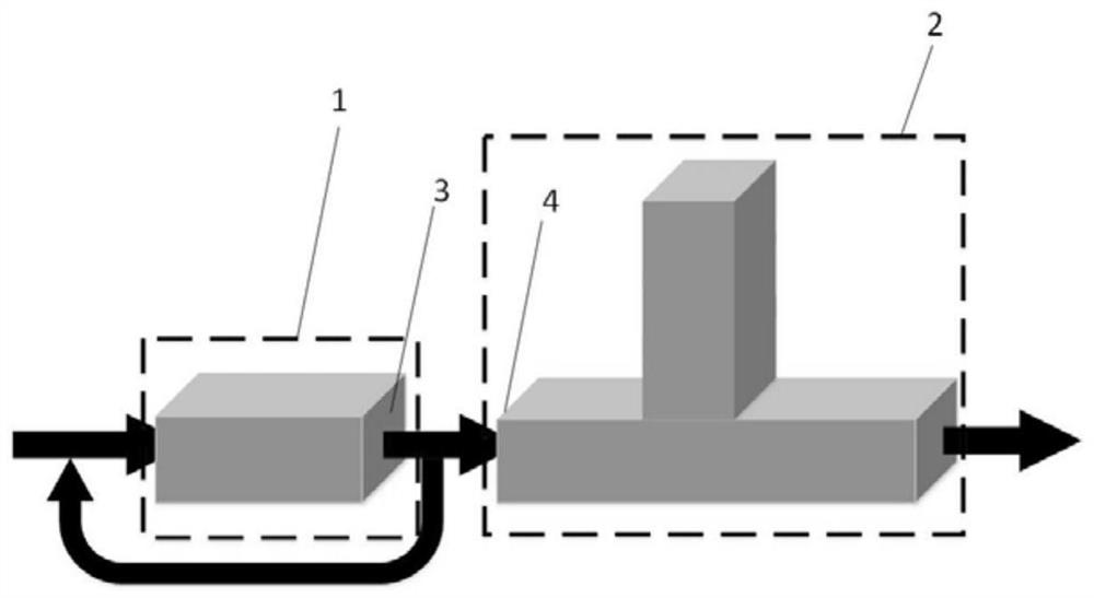
[0023] combine Figure 1-2 , the purpose of the present invention is to optimize the method of calculating the flow field characteristics of the closed branch pipeline system to a certain extent, to ensure that the turbulent flow in the pipeline is fully developed, and at the same time reduce the amount of grids increased due to the extension of the pipeline, ensure the quality of the grid, and fully Reasonable use of existing computing resources can reduce the amount of calculation, and can more accurately give the boundary conditions of the pipeline flow field, so as to better simulate the flow in the real pipeline. The specific steps are as follows:

[0024] Step 1: Numerical simulation pre-processing, complete the modeling and grid division of the calculation domain, and divide the simulation domain into two parts: the cycle area 1 and the actual pipeline cal...


PUM


Abstract

The invention aims to provide a numerical simulation method for calculating flow field characteristics of a closed bypass pipeline system. The method comprises the following steps of: performing numerical simulation pretreatment, completing modeling and grid division on a computational domain, and performing modeling and flow field grid division on the computational domain; initializing a periodic circulation area, and setting a strip-shaped speed; carrying out numerical iterative calculation, calculating a periodic circulation region, and extracting the three-way speed of an outlet of the periodic circulation region after each time step; if the turbulence is not fully developed, continuing numerical iterative calculation; if the turbulence is fully developed, assigning an outlet velocity boundary of the periodic circulation region to an inlet of the actual pipeline calculation region as an inlet boundary condition of the actual calculation region; and carrying out numerical calculation of an actual pipeline area, and completing subsequent flow field characteristic calculation and post-processing. According to the method, the grid quantity increased due to pipeline extension is reduced, and the boundary conditions of the pipeline flow field can be more accurately given, so that flowing in a real pipeline is better simulated.

Description

technical field [0001] The invention relates to a pipeline simulation method, in particular to a closed bypass pipeline flow simulation method. Background technique [0002] The flowing medium in the main pipeline of the primary circuit of the nuclear power system is usually high temperature and high pressure fluid. In order to ensure the safe operation of the nuclear power system, a pressure relief pipeline is usually installed at a specific position in the main pipeline. Generally, one section of the pressure relief pipeline is connected to the main pipeline, and the other end is in the Normally, it is closed, which forms the special structure of closed side branch pipeline. [0003] When the fluid flows through the specific structure of the closed bypass pipe, vortices will be generated and shed periodically. When the fluid excitation generated by the frequency of vortex shedding is close to the frequency of the acoustic mode, a "frequency locking phenomenon" will occur, ...

Claims


Application Information

Patent Timeline
IPC IPC(8): G06F30/17G06F30/23G06F30/28G06F111/10G06F113/14G06F113/08G06F119/14
CPCG06F30/17G06F30/23G06F30/28G06F2111/10G06F2113/14G06F2113/08G06F2119/14Y02T90/00
Inventor 李玩幽殷文慧率志君王曦曹宏博于涛任可欣
Owner HARBIN ENG UNIV
Why Eureka
Try Eureka