
Control method for improving oil shortage of compressor during starting of water-free floor heating unit and triple co-generation system

A control method and compressor technology, which is applied to compressors, heating systems, refrigerators, etc., can solve problems such as insufficient lubrication of compressors, insufficient compressor oil, and reduced service life, so as to avoid unstable operation of the system and reduce The effect of oil displacement

Active Publication Date: 2021-11-19
ZHEJIANG ZHONGGUANG ELECTRIC CO LTD
View PDF18 Cites 1 Cited by
  • Summary
  • Abstract
  • Description
  • Claims
  • Application Information

AI Technical Summary

Problems solved by technology

[0003] In the existing waterless floor heating capillary network system, the number of capillaries is large, and the amount of liquid added is large, generally 2 to 3 times that of conventional units. The amount of liquid added to the refrigerant is too large, and there will be a large amount of liquid when starting, especially when the outdoor ambient temperature is low. Liquid back, resulting in insufficient compressor oil, insufficient lubrication during compressor operation, increased wear, and reduced service life, which in turn affects the reliability of the entire system operation

Method used


Image

  • Control method for improving oil shortage of compressor during starting of water-free floor heating unit and triple co-generation system
  • Control method for improving oil shortage of compressor during starting of water-free floor heating unit and triple co-generation system
  • Control method for improving oil shortage of compressor during starting of water-free floor heating unit and triple co-generation system

Examples


Embodiment Construction

[0020] In order to have a clearer understanding of the technical features, purposes and effects of the present invention, the specific implementation manners of the present invention will be described in detail below in conjunction with the accompanying drawings.

[0021] It should be noted that the terms "first" and "second" herein are used for description purposes only, and cannot be understood as indicating or implying relative importance or implicitly indicating the quantity of indicated technical features. Thus, a feature defined as "first" and "second" may explicitly or implicitly include one or more of these features. In the description of the present application, "plurality" means two or more, unless otherwise specifically defined.

[0022] Unless otherwise defined, all technical and scientific terms used herein have the same meaning as commonly understood by one of ordinary skill in the technical field of the invention. The terms used herein in the description of the...


PUM


Abstract

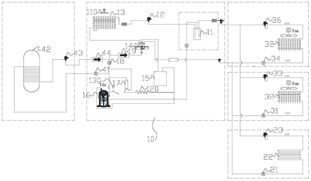
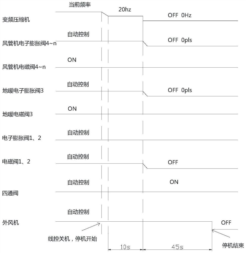
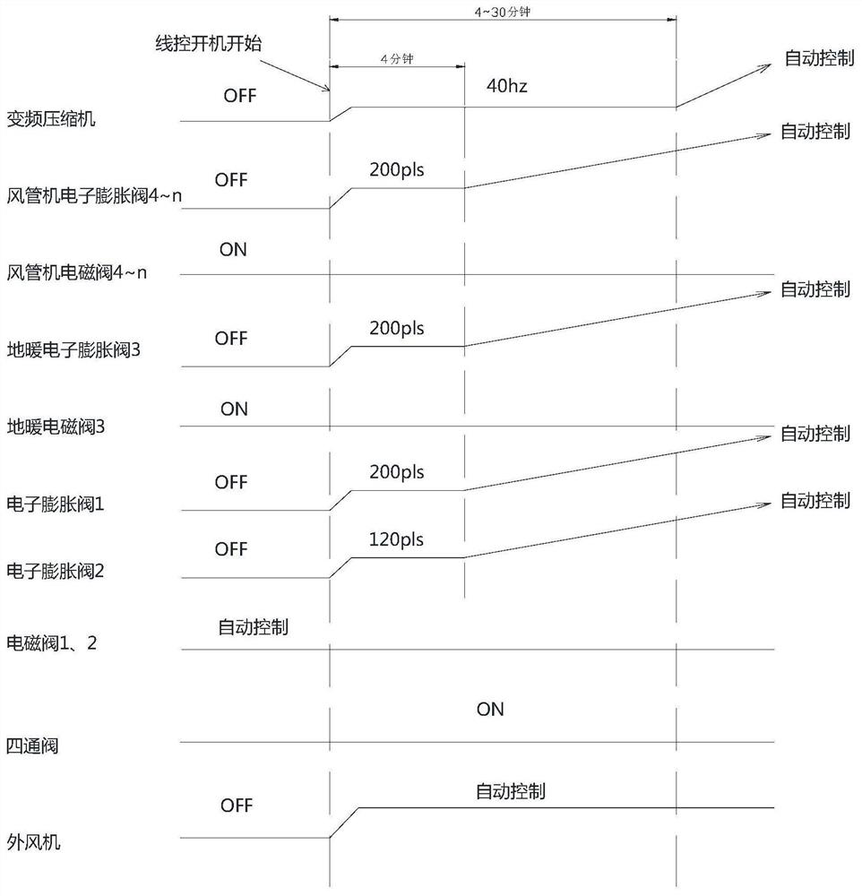
The invention relates to a control method for improving oil shortage of a compressor during starting of a water-free floor heating unit and a triple co-generation system thereof. The triple co-generation system comprises a heat pump external unit and a water-free floor heating unit used for indoor heating. The external unit comprises the compressor, an outdoor heat exchanger, an outdoor fan and a first electronic expansion valve. The exhaust end of the compressor is connected with an oil separator in series. An oil return capillary pipe is arranged on a refrigerant pipeline, bypassing the oil separator to the air inlet end of the compressor. A first electromagnetic valve and a first one-way valve are sequentially arranged on the refrigerant outlet side of the oil separator. A second electromagnetic valve used for controlling on-off of a refrigerant is arranged on the refrigerant inlet side of the water-free floor heating unit, and a second electronic expansion valve is arranged on the refrigerant outlet side of the water-free floor heating unit. According to the control method, when the external unit receives a water-free floor heating shutdown command, most of the refrigerant in the system is stored in the floor heating capillary pipe, and the problem of a large amount of liquid return during starting is solved; and when the external unit receives a water-free floor heating starting command, the unit is controlled to be softly started to operate, and oil discharge of the compressor is reduced.

Description

technical field [0001] The invention relates to a waterless floor heating heat pump unit, in particular to a method for controlling oil shortage of a compressor when the waterless floor heating unit starts up and a triple supply system thereof. Background technique [0002] Waterless floor heating is favored by consumers because of its comfort, energy saving and environmental protection, low operating costs, and no risk of waterway freezing in winter. The compressor is the core driving component of the common waterless floor heating heat pump units on the market. Sufficient oil quantity is required to guarantee the lubrication effect of internal parts. [0003] In the existing waterless floor heating capillary network system, the number of capillaries is large, and the amount of liquid added is large, generally 2 to 3 times that of conventional units. The amount of liquid added to the refrigerant is too large, and there will be a large amount of liquid when starting, especia...

Claims


Application Information

Patent Timeline
IPC IPC(8): F24D15/04F24D19/10F25B30/02F25B31/00F25B41/20F25B41/24F25B41/34F25B49/02
CPCF24D15/04F24D19/10F25B30/02F25B41/24F25B41/20F25B41/34F25B31/004F25B49/02F24D2200/123Y02B10/70Y02B30/12Y02B30/70
Inventor 叶方明钟延龙叶昌正夏柱君
Owner ZHEJIANG ZHONGGUANG ELECTRIC CO LTD
Learn More