
Street lamp device with automatic time setting function

A street lamp, automatic technology, applied in lighting devices, circuit layouts, fixed lighting devices, etc., can solve the problems of white LED street lights, the safety of passers-by, and the inability to switch street lights.

Pending Publication Date: 2021-11-19
ORING IND NETWORKING CORP
View PDF0 Cites 0 Cited by
  • Summary
  • Abstract
  • Description
  • Claims
  • Application Information

AI Technical Summary

Problems solved by technology

[0004] However, humans have adapted to receive light from blue sky and white clouds during the day (high color temperature), reddish-yellow light at dusk (medium-low color temperature), and light yellow and red light from moonlight and fire at night (medium-low color temperature) ), and street lights will make people misunderstand, thinking that it is daytime, the influence of dim yellow light in the past is relatively small, and the impact of white LED street lights will be greater after the popularity
[0005] Moreover, the current street lights cannot be switched on and off according to the time of sunset and sunrise. Sometimes after midnight (about 12:00 in the middle of the night), there are not many pedestrians on the road. It should be possible to reduce the light intensity to achieve The effect of energy saving and carbon reduction, but the current street lamps cannot make such adjustments
[0006] In addition, the relationship between the seasons will also make the sunset time different, resulting in slight changes in the time when the lights should be turned on and off every day. However, the current street lights can only be turned on and off according to a fixed time, which is very inconvenient. If it is winter The sun will set earlier, but the street lights have not yet been turned on. At this time, the safety of passers-by is worrying.

Method used


Image

  • Street lamp device with automatic time setting function
  • Street lamp device with automatic time setting function
  • Street lamp device with automatic time setting function

Examples


Embodiment Construction

[0039] In order to make the structural features of the present invention and the achieved effects have a further understanding and recognition, preferred embodiments and detailed descriptions are specially used, which are described as follows:

[0040] Conventional street lights cannot be turned on and off according to seasonal changes, and the current street lights can only be turned on and off according to a fixed time, which makes passers-by feel very inconvenient. It falls early, but the street lights have not yet been turned on, which will cause unsafe use of passers-by.

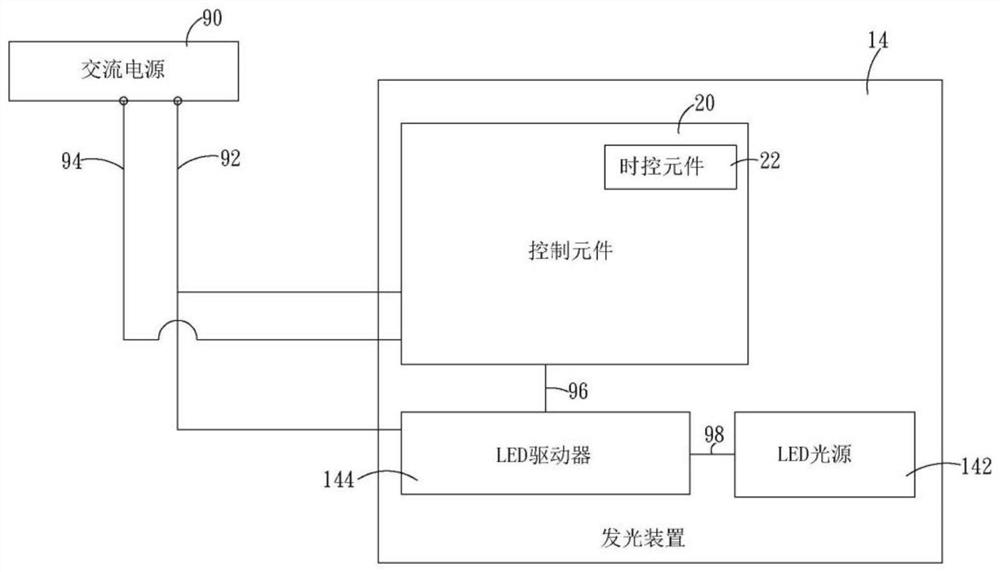
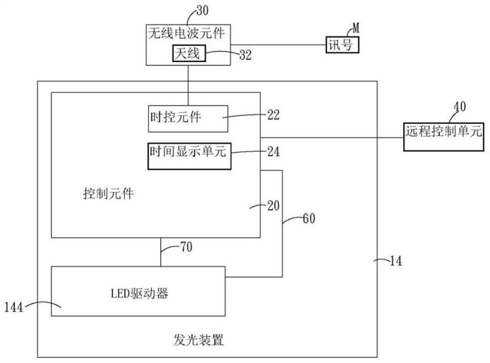
[0041] The street light device of the present invention can receive radio waves through the radio wave element, and transmit the information containing the standard time transmitted by the time base station to the control element in the street light so that the time in the street light is the same as the standard time.

[0042] Hereinafter, the present invention will be described in detail by illustrati...


PUM


Abstract

The invention relates to a street lamp device with an automatic time setting function, which structurally comprises a street lamp and a control element, the street lamp is electrically connected with a first power supply end of an alternating current power supply, the street lamp is provided with a lamp post, one end of the lamp post is provided with a light-emitting device, and the control element is electrically connected with the first power supply end and a second power supply end of the alternating current power supply. A third power supply end of the control element is electrically connected with the light-emitting device, the control element further comprises a radio wave element, the radio wave element is provided with an antenna, the radio wave element is electrically connected with a time control element in the control element, the radio wave element receives a signal of 30 KHz to 300 KHz through the antenna, and the time control element corrects a time according to the signal.

Description

technical field [0001] The invention relates to a device, in particular to a street lamp device for automatic time adjustment. Background technique [0002] Traditional street lamps, also known as street lamps, are luminous lighting systems on roads, streets and public squares. It usually turns on at night or when it gets dark, and turns off after dawn. The basic function of street lights is lighting, and its additional functions can be works of art, landmarks, road signs, telephone booths, message boards, letter boxes, assembly points, advertising light boxes, smart lampposts, etc. [0003] The biggest advantage of street lamps is that they can prevent accidents and crimes, assist security, police, CCTV surveillance, video, video, etc. Historically, street lamps used gas, torches, candlesticks, lanterns, etc. In recent years, most of them are filled with inert gas Light-emitting diode (LED) street lights are used in some places to save electricity. [0004] However, huma...

Claims


Application Information

Patent Timeline
Patent Type & Authority Applications(China)
IPC IPC(8): F21S8/08F21V23/04H05B45/30F21W131/103F21Y115/10
CPCF21S8/088F21V23/0435H05B45/30F21W2131/103F21Y2115/10Y02B20/40
Inventor 陈俊道杨明儒林佩仪罗景煜蔡孟颖洪崇元杨志伟赖建薳林柏均许家声刘泓毅林政霆林智纬李佳蓉黄茂峰
Owner ORING IND NETWORKING CORP
Learn More