Plastering machine facilitating waste recovery
A technology of recycling waste and plastering machines, which is applied in the direction of construction and building construction, can solve the problem of wall scraping without recycling waste and cannot be finished with mortar, and achieve the effect of saving resources and reducing resource waste
- Summary
- Abstract
- Description
- Claims
- Application Information
AI Technical Summary
Problems solved by technology
Method used
Image
Examples
Embodiment 1
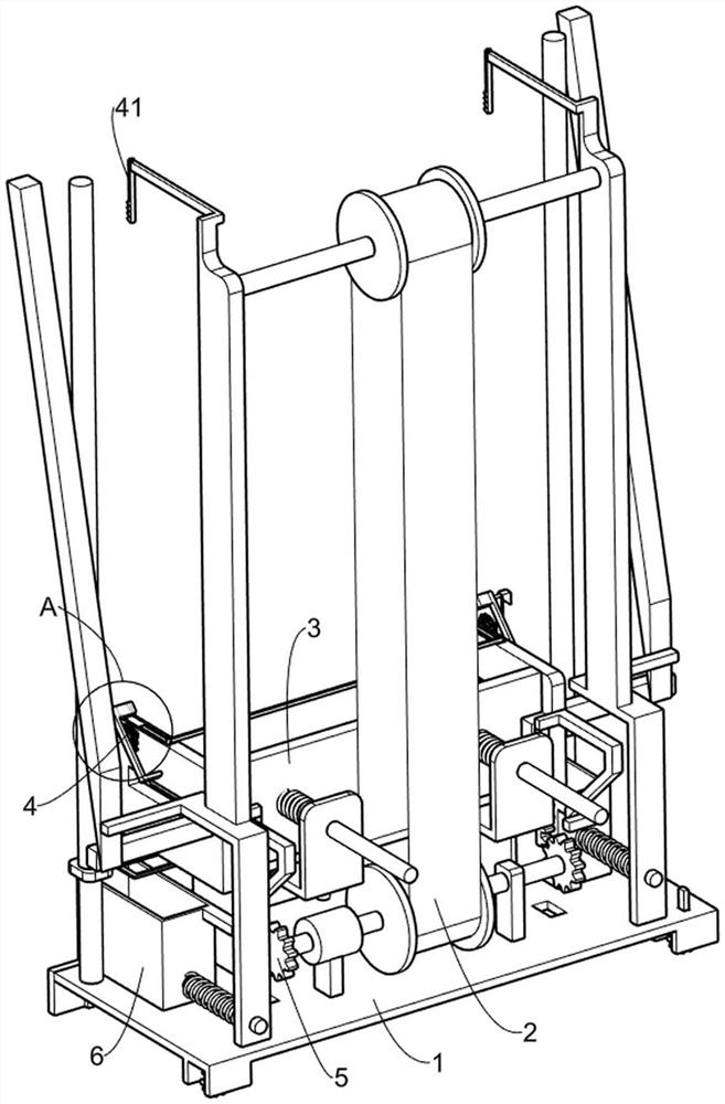
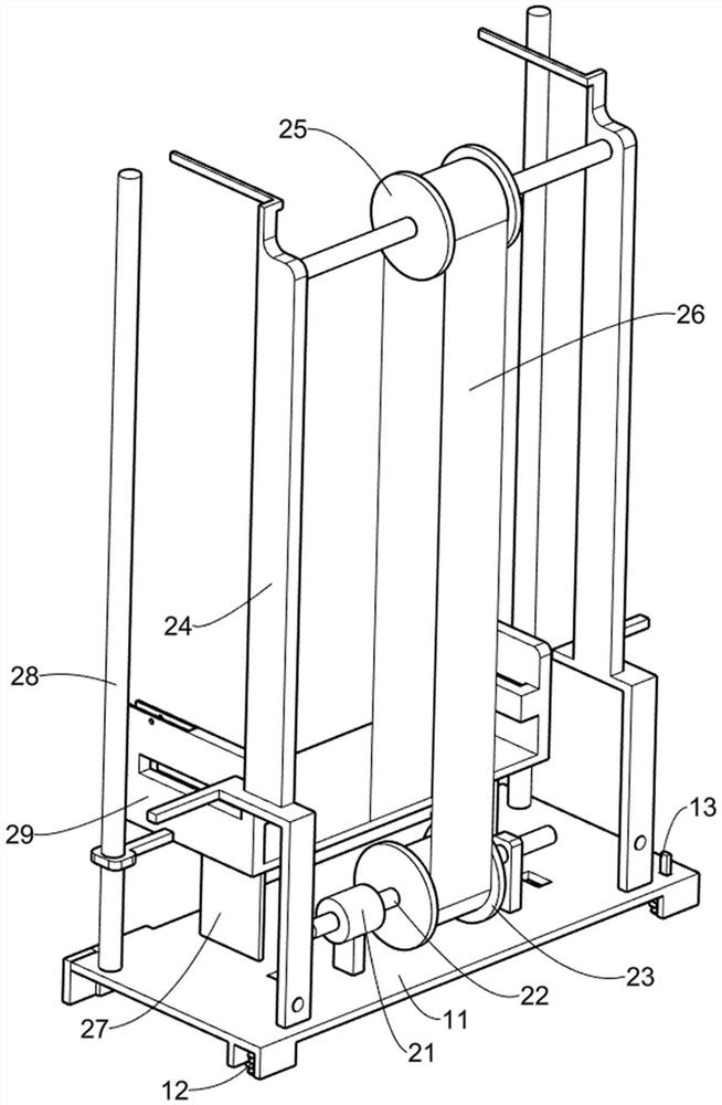
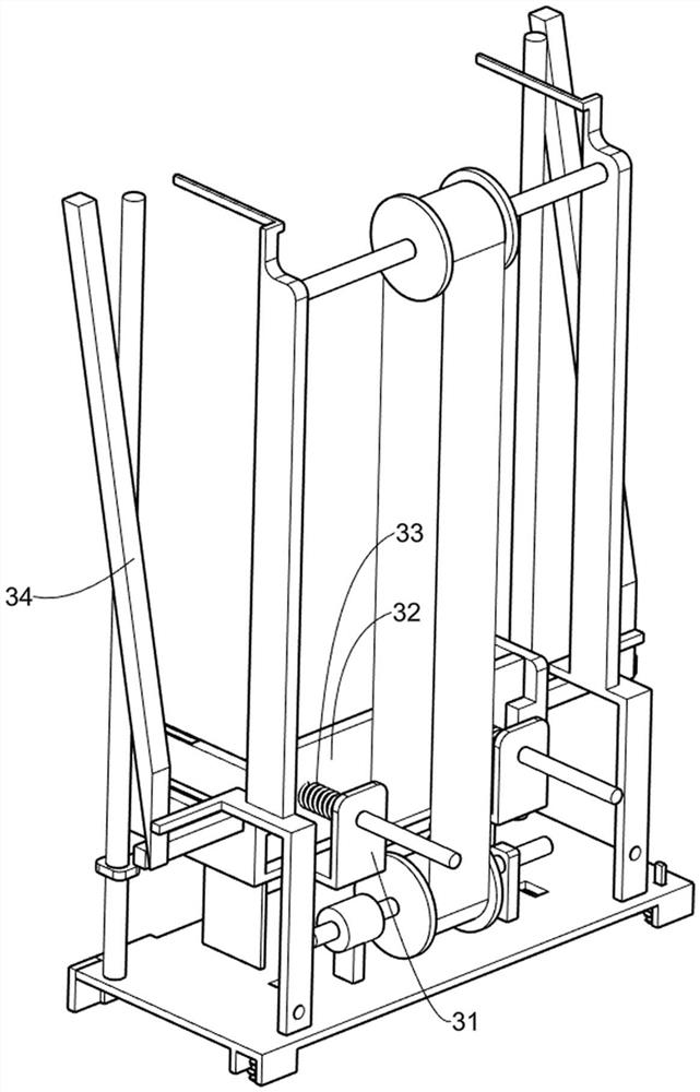
[0027] A plastering machine that facilitates the recycling of waste materials such as Figure 1-4 As shown, it includes a moving mechanism 1, a lifting mechanism 2 and a pushing mechanism 3. The moving mechanism 1 is provided with a lifting mechanism 2. The lifting mechanism 2 is used to smear the mortar on the first sliding frame 29 on the wall. The lifting mechanism 2 There is a driving mechanism 3 on it.
[0028] The moving mechanism 1 includes a fixed plate 11, a first rotating wheel 12 and a block 13, a pair of first rotating wheels 12 are rotatably connected to the fixed plate 11, and a block 13 is slidably connected to the fixed plate 11, and the block 13 blocks One of the first rotating wheels 12 is lived.
[0029] Lifting mechanism 2 comprises two-way motor 21, the first rotating shaft 22, the second rotating wheel 23, the first fixed mount 24, the third rotating wheel 25, rotating belt 26, the second fixed mount 27, the first fixed rod 28 and the first fixed rod 28....
Embodiment 2
[0033] On the basis of Example 1, such as Figure 4-5 Shown, also comprise the first leveling mechanism 4, the first leveling mechanism 4 is located on the lifting mechanism 2, the first leveling mechanism 4 is used for scraping the wall surface that is coated with mortar, the first leveling mechanism 4 Including a first rack 41, a fixed ring 42, a first gear 43, a second rotating shaft 44, a first wedge block 45, a second return spring 46, a scraper 47, a torsion spring 48, a fourth fixed frame 49, a second Wedge block 411, the 4th back-moving spring 412, the 3rd wedge block 413 and the second fixed bar 414, the first fixed frame 24 is connected with a pair of first tooth bar 41, under the effect of the first tooth bar 41, the first gear 43 can reverse 120 °, the first sliding frame 29 is connected with a pair of fixed rings 42, the fixed ring 42 is connected with the first gear 43 in a rotational manner, and the first gear 43 is used to drive the first wedge block 45 and its...
Embodiment 3
[0037] On the basis of Example 2, such as Figure 6 As shown, it also includes a second scraping mechanism 5, the second scraping mechanism 5 is located on the lifting mechanism 2, the second scraping mechanism 5 is used to scrape the lower part of the wall, and the second scraping mechanism 5 includes the first Two gears 51, the second fixed rod 52, the third sliding frame 53, the fifth return spring 54 and the second rack 55, the other output shaft end of the bidirectional motor 21 is connected with the second gear 51, the second gear 51 is used to drive The second rack 55 and its upper device move downwards. One end of the first rotating shaft 22 is also connected with the second gear 51. The bottom of the first sliding frame 29 is connected with the second fixed rod 52. The second fixed rod 52 is slidably connected. There is a third sliding frame 53, the third sliding frame 53 is used to scrape the lower part of the wall, the third sliding frame 53 is in contact with the f...
PUM
 Abstract
Description
Claims
Application Information
 - R&D
- Intellectual Property
- Life Sciences
- Materials
- Tech Scout
- Unparalleled Data Quality
- Higher Quality Content
- 60% Fewer Hallucinations
Browse by: Latest US Patents, China's latest patents, Technical Efficacy Thesaurus, Application Domain, Technology Topic, Popular Technical Reports.
© 2025 PatSnap. All rights reserved.Legal|Privacy policy|Modern Slavery Act Transparency Statement|Sitemap|About US| Contact US: help@patsnap.com


