
Automatic stamp-pad ink painting device of stamping machine

A technology of stamping machine and ink, applied in printing, stamping and other directions, can solve problems such as non-compliance with ergonomic requirements, long stamping cycle, prone to mechanical failures, etc., to achieve efficient design, simple and ingenious design structure , the effect of taking up less space

Inactive Publication Date: 2014-10-08
SICHUAN CHANGHONG ELECTRIC CO LTD
View PDF11 Cites 1 Cited by
  • Summary
  • Abstract
  • Description
  • Claims
  • Application Information

AI Technical Summary

Problems solved by technology

However, under the condition of continuous high-speed stamping, the cam-link compound drive mechanism is prone to mechanical failure, and the mechanism is relatively large, which does not meet the ergonomic requirements of office equipment; the utility model patent publication with the publication number CN203485592U A kind of ink box assembly used in stamping machine is proposed. In this scheme, the ink box is limited in the special-shaped through hole of the frame and can rotate around the axis. Under the driving, the ink box slides along the inner edge of the through hole to the correct position to align the stamp Replenish the ink, the structure is simple, the effect is good, but each time after the ink is replenished, the stamp can only be moved down to complete the stamp after the ink box is completely away from the bottom of the stamp, which makes the cycle of one stamping longer, which is not conducive to continuous high-speed automatic capping chapter

Method used


Image

  • Automatic stamp-pad ink painting device of stamping machine
  • Automatic stamp-pad ink painting device of stamping machine
  • Automatic stamp-pad ink painting device of stamping machine

Examples


Embodiment

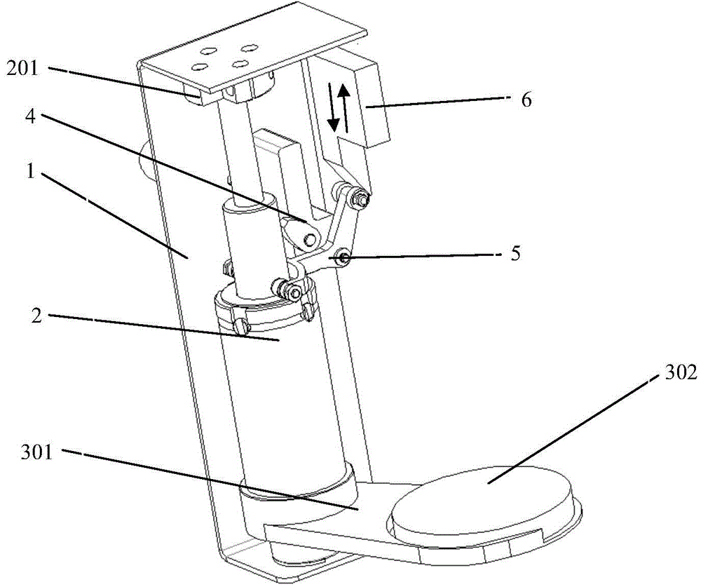
[0027] The ink automatic smearing device of the stamping machine in this example, such as figure 1 As shown, the structure includes a mounting frame body 1, a sliding mechanism 2, an ink tray 301, an ink tray 302, and a driving mechanism. The sliding mechanism (2) and the driving mechanism are all installed on the mounting frame body (1). The tray (302) is fixed on the shaft sleeve (203) of the sliding mechanism (2), the ink tray (302) is arranged on the ink tray (301), and the driving mechanism and the sliding mechanism (2) are contact-fitted.

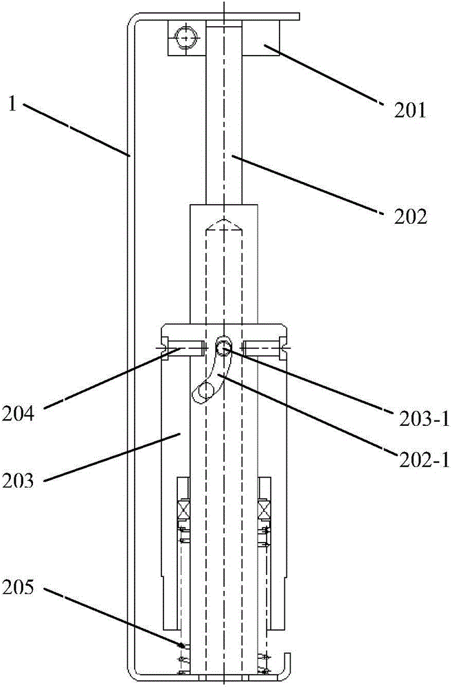
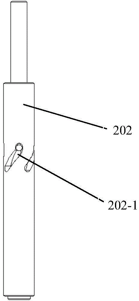
[0028] Specifically, the sliding mechanism 2, such as Figure 2-3 As shown, it includes a sliding shaft 202, a shaft sleeve 203, and an elastic mechanism 205 fixed on the mounting bracket body 1 by means of a fixing flange 201. The sliding shaft 202 is evenly provided with four spiral grooves 202-1, and the shaft The sleeve 203 is provided with a through hole 203-1 corresponding to the helical groove 202-1, with the help of the dial ...


PUM


Abstract

An automatic stamp-pad ink painting device of a stamping machine relates to automatic office devices. The device aims at solving the problem in the prior art that manual stamping is high in workload, low in working efficiency, poor in stamping effect and prone to stamping position variation. A sliding mechanism and a driving mechanism are both installed on an installation frame body. The sliding mechanism comprises a sliding shaft, a shaft sleeve and an elastic mechanism. Four spiral grooves are evenly formed in the sliding shaft, through holes corresponding to the spiral grooves are formed in the shaft sleeve, poking pins sequentially penetrate the through holes and the spiral grooves to enable the shaft sleeve and the sliding shaft to form spiral match, two ends of the sliding shaft are arranged at two ends of the inner side of the installation frame body, the elastic mechanism is arranged between the shaft sleeve and the sliding shaft, one end of the elastic mechanism is connected with the shaft sleeve, the other end abuts against the installation frame body, the elastic mechanism can push the shaft sleeve to enable the shaft sleeve to be reset, a stamp-pad ink tray is fixed on the shaft sleeve of the sliding mechanism, a stamp-pad ink disc is arranged on the stamp-pad ink tray, and the driving mechanism and the sliding mechanism are in contact match.

Description

technical field [0001] The invention relates to the field of automated office equipment, in particular to an automatic printing ink application device used in a stamping machine. Background technique [0002] Under the background of the rapid development of the market economy, listed companies often need to stamp the official seal of the company, especially the tens of thousands of pages of tender documents, which need to be stamped on each page. If the stamp is manually stamped, not only the workload is heavy, the work efficiency is low, and the stamping effect Very poor, it is easy to cause the seal position to be different. [0003] At present, most of the stamping machines on the market use rolling printing. This kind of stamping machine is not only difficult to process and requires high precision, but also the rolling seal does not meet the requirements of the company's official seal in relevant laws and regulations, which is extremely unsafe. Some researchers have pro...

Claims


Application Information

Patent Timeline
Patent Type & Authority Applications(China)
IPC IPC(8): B41K3/54
Inventor 李宗泽王川濮湛华
Owner SICHUAN CHANGHONG ELECTRIC CO LTD
Learn More