
Switching power amplifier and control method and control system thereof

A switching power and amplifier technology, applied in the field of power supply in electrical engineering, can solve the problems of increasing the volume and cost of switching power amplifiers, increasing the complexity of control links, increasing the volume and price of devices, etc., achieving enhanced capabilities and improving output waveforms Quality, the effect of reducing voltage fluctuations

Active Publication Date: 2021-11-16
GUANGDONG ZHICHENG CHAMPION GROUP
View PDF7 Cites 1 Cited by
  • Summary
  • Abstract
  • Description
  • Claims
  • Application Information

AI Technical Summary

Problems solved by technology

However, this method will lead to a substantial increase in the size and cost of the switching power amplifier
In recent years, the review and comparison of invention patent applications in the field of switching power amplifier power decoupling is as follows: "Single-phase grid-connected inverter with active power decoupling function and power decoupling method" (public number: CN104104256A, publication date: October 15, 2014), it can realize the decoupling of DC power and AC power by connecting a half-bridge converter in parallel next to the DC capacitor, but it needs to configure an additional half-bridge converter and a snubber capacitor, which increases the device size and price
"Current Compensation Method, Power Decoupling Circuit, and Power Converter System" (public number: CN110690812A, public date: January 14, 2020), which controls the voltage on the capacitor by connecting a full-bridge converter in series with the DC capacitor fluctuations, but this method requires an additional full-bridge converter, and the complexity of the control link is greatly increased

Method used


Image

  • Switching power amplifier and control method and control system thereof
  • Switching power amplifier and control method and control system thereof
  • Switching power amplifier and control method and control system thereof

Examples


Embodiment Construction

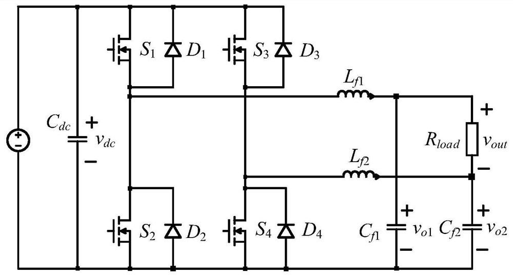
[0036] Such as figure 2 As shown, the dual BUCK switching power amplifier of the embodiment of the present invention includes a first capacitor Cdc , by 2 switching devices S 1 , S 2 , filter inductance L f1 and filter capacitor C f1 The first BUCK circuit (that is, the first branch) composed of two switching devices S 3 , S 4 , filter inductance L f2 and filter capacitor C f2 The second BUCK circuit (i.e. the second branch) formed; the first capacitor is connected with the input terminals of the first BUCK circuit and the second BUCK circuit, and the output terminal is composed of the positive pole of the output capacitor of the first BUCK circuit and the output terminal of the second BUCK circuit positive terminal of the output capacitor. In this embodiment, the switching device S 1 ~S 4 Using wide bandgap devices. The first filter inductor is connected to the first filter capacitor, the second filter inductor is connected to the second filter capacitor; the first...


PUM


Abstract

The invention discloses a switching power amplifier and a control method and a control system thereof. A BUCK circuit output capacitor is used as an energy buffer link, unbalanced energy of an input side and an output side is balanced, and meanwhile, a rated voltage is tracked by controlling an output voltage difference value of two BUCK circuits, so that the waveform quality of the output voltage is ensured. The number of power devices and passive devices required by the two BUCK circuits is the same with that of a conventional single-phase inverter, meanwhile, voltage and current ripples of a direct-current bus are effectively restrained, power decoupling is achieved, and the application range is wide.

Description

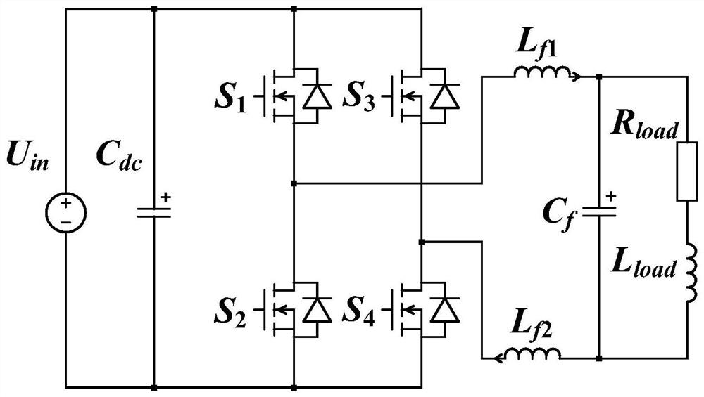
technical field [0001] The invention relates to the field of power supply technology in electrical engineering, in particular to a switching power amplifier and its control method and control system. Background technique [0002] The traditional switching power amplifier structure such as figure 1 shown. which includes the energy storage capacitor C dc , two half-bridge circuits S composed of four power devices 1 , S 2 and S 3 , S 4 , two filter inductors L f1 , L f2 and a filter capacitor C f . Energy storage capacitor C dc with the power device S 1 , S 2 The first half-bridge circuit formed in series is connected in parallel, and the first half-bridge circuit is connected with the S 3 , S 4 The second half-bridge circuit formed in series is connected in parallel. Two filter inductors at one end L f1 , L f2 Connect the midpoints of the first half-bridge circuit and the second half-bridge circuit respectively (that is, the output end of the half-bridge circu...

Claims


Application Information

Patent Timeline
Patent Type & Authority Applications(China)
IPC IPC(8): H02M7/5387H02M3/158H02M3/157H02M1/12
CPCH02M7/5387H02M7/53871H02M7/53873H02M3/157H02M3/158H02M3/1584H02M1/126Y02B70/10
Inventor 徐千鸣胡家瑜罗安郭鹏李加东陈燕东何志兴李民英
Owner GUANGDONG ZHICHENG CHAMPION GROUP
Learn More