
In-vehicle air noise target decomposition method based on transfer path analysis theory

A technology for transfer path analysis and in-vehicle air, applied in constraint-based CAD, internal combustion piston engine, special data processing applications, etc., can solve the problems of performance waste, high cost, heavy workload, etc., to save development time and production cost, the effect of taking into account decomposition accuracy and decomposition efficiency

Pending Publication Date: 2021-11-16
CATARC TIANJIN AUTOMOTIVE ENG RES INST CO LTD +1
View PDF0 Cites 1 Cited by
  • Summary
  • Abstract
  • Description
  • Claims
  • Application Information

AI Technical Summary

Problems solved by technology

Although the benchmarking method has the ability to decompose the noise in the car in a certain sense, it has a series of problems such as high cost, low precision, heavy workload, and waste of performance.
[0004] Transfer path analysis is an important means of air noise control in the car, but it requires complete sound source excitation and transfer function data. In the early stage of vehicle development, the complete data of sound source excitation and transfer function cannot be obtained. Obviously, the traditional transfer path analysis method Cannot be directly used to achieve the target decomposition of airborne noise in the car

Method used

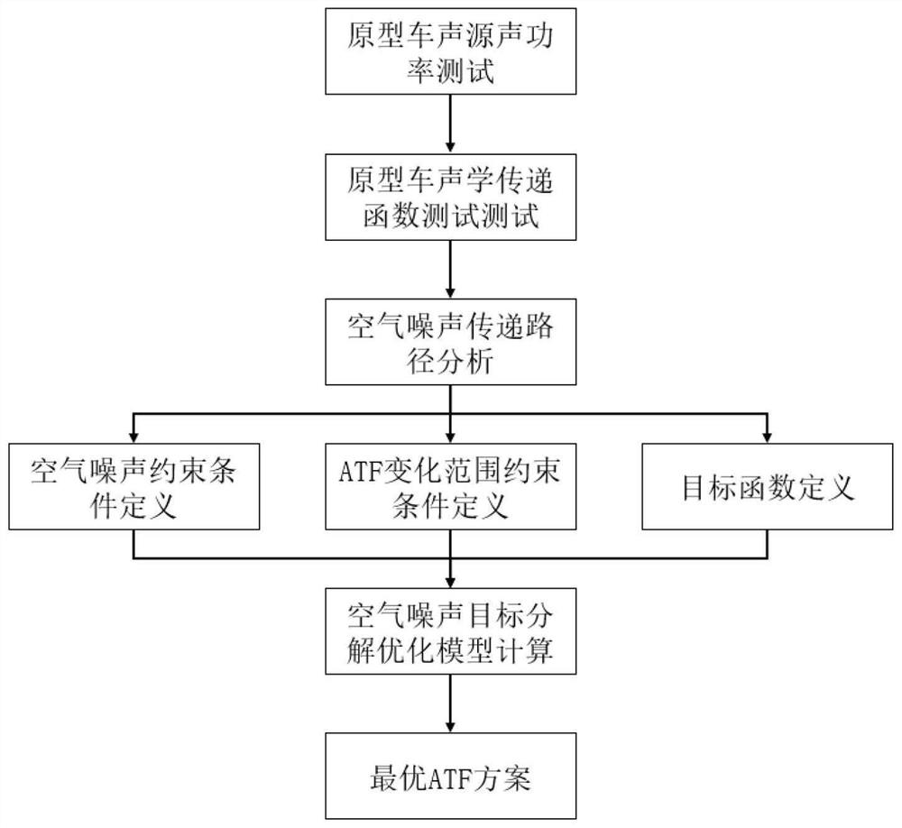

Image

  • In-vehicle air noise target decomposition method based on transfer path analysis theory
  • In-vehicle air noise target decomposition method based on transfer path analysis theory
  • In-vehicle air noise target decomposition method based on transfer path analysis theory

Examples


Embodiment Construction

[0045] It should be noted that, in the case of no conflict, the embodiments of the present invention and the features in the embodiments can be combined with each other.

[0046] The present invention will be described in detail below with reference to the accompanying drawings and examples.

[0047] The applicant gave an embodiment of the present invention according to the specific vehicle model development process. The research object is a front-wheel-drive car with a four-cylinder turbocharged engine with a maximum power of 188 horsepower and a peak torsional vibration of 275 Nm.

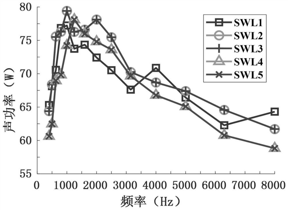
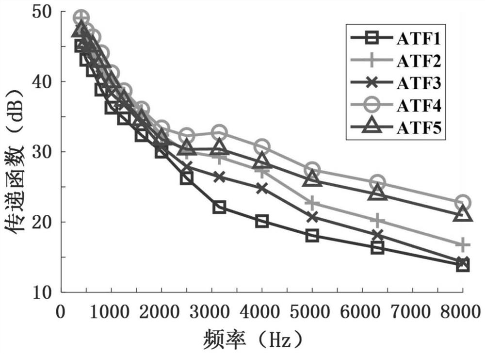
[0048] Step 1: Test the sound source sound power and acoustic transfer function data of the prototype vehicle. The sound source sound power test results are as follows: figure 2 As shown, the acoustic transfer function test results are as follows image 3 shown.

[0049] Step 2: Based on the analysis theory of the air noise transfer path, sort out the decibel relationship among the sound power...


PUM


Abstract

The invention provides an in-vehicle air noise target decomposition method based on a transfer path analysis theory. The method comprises the following steps: S1, measuring prototype vehicle sound source sound power and acoustic transfer function data, establishing a transfer path analysis model, and calculating in-vehicle air noise based on a transfer path analysis theory; and S2, establishing an air noise target decomposition optimization model, customizing a target function according to an actual demand by taking the acoustic transfer function of each path as a design variable and the air noise target in the vehicle as a constraint condition, and performing automatic optimization by adopting a multi-island genetic algorithm to obtain an optimal acoustic transfer function scheme. The method has the advantages that the transmission path analysis and automatic optimization theory is applied for the first time in the field of in-vehicle air noise target decomposition of the automobile, a large number of tests in the traditional experience development process are omitted, the development time and production cost of the whole automobile are saved, meanwhile, the optimal solution of the transmission path can be found through an optimization algorithm, and the phenomenon of performance waste caused by unreasonable performance distribution of the factor system is avoided.

Description

technical field [0001] The invention belongs to the field of automobile NVH performance development, and in particular relates to an air noise target decomposition method in a car based on a transfer path analysis theory. Background technique [0002] With the development of intelligent technology, cars have become more and more people's daily life space, and the NVH performance of cars is becoming more and more important. The NVH performance of automobiles can be divided according to the frequency. Below 100Hz, the main problem that affects people's perception is the vibration problem. Below 400Hz, the structural noise caused by structural vibration dominates. Above 400Hz, the air noise transmitted through the air is the vehicle interior. major components of noise. Therefore, effective control of air noise in the vehicle is of key significance for the development of vehicle NVH performance. [0003] Vehicle air noise control first requires target decomposition, that is, t...

Claims


Application Information

Patent Timeline
IPC IPC(8): G06F30/20G06F111/04G06F119/10
CPCG06F30/20G06F2111/04G06F2119/10Y02T10/40
Inventor 郝耀东陈达亮李洪亮赵梓廷邓江华杨征睿顾灿松董俊红苏丽俐杨明辉胡常青耿聪聪凌子红
Owner CATARC TIANJIN AUTOMOTIVE ENG RES INST CO LTD
Learn More