
Shear vibration-ultrasonic composite sensor and measuring device

A composite sensor, shearing technology, applied in the field of sensor detection, can solve the problems of not being able to accurately obtain multiple physical parameters of equipment at the same time, difficult to comprehensively reflect the comprehensive operating state of the equipment, and limited types of detected faults, and achieve strong strain resistance. , low cost, high signal-to-noise ratio

Active Publication Date: 2022-05-06
XI AN JIAOTONG UNIV
View PDF11 Cites 0 Cited by
  • Summary
  • Abstract
  • Description
  • Claims
  • Application Information

AI Technical Summary

Problems solved by technology

[0003] Generally speaking, the operating status of equipment is jointly affected by various factors such as electrical and mechanical. However, the current equipment fault diagnosis method is mainly based on the detection of a single physical quantity to evaluate the equipment status. This method has poor accuracy and limited types of fault detection. The multi-physical parameters of a certain point on the device cannot be obtained accurately at the same time, and it is difficult to fully reflect the comprehensive operating state of the device; the current acceleration piezoelectric sensor structure is mainly compressed, and the structure is relatively simple, because the piezoelectric element is directly placed on the sensor base , noise, base strain and other interference signals have a strong impact on the measurement of the sensor

Method used


Image

  • Shear vibration-ultrasonic composite sensor and measuring device
  • Shear vibration-ultrasonic composite sensor and measuring device
  • Shear vibration-ultrasonic composite sensor and measuring device

Examples


Embodiment Construction

[0038] In order to make the purpose, technical solutions and advantages of the embodiments of the present invention more clear, the following will be combined with the accompanying drawings in the embodiments of the present invention Figure 1 to Figure 6 , clearly and completely describe the technical solutions in the embodiments of the present invention, obviously, the described embodiments are part of the embodiments of the present invention, but not all of them. Based on the implementation manners in the present invention, all other implementation manners obtained by persons of ordinary skill in the art without creative efforts fall within the protection scope of the present invention.

[0039] Accordingly, the following detailed description of the embodiments of the invention provided in the accompanying drawings is not intended to limit the scope of the claimed invention, but merely represents selected embodiments of the invention. Based on the implementation manners in ...


PUM


Abstract

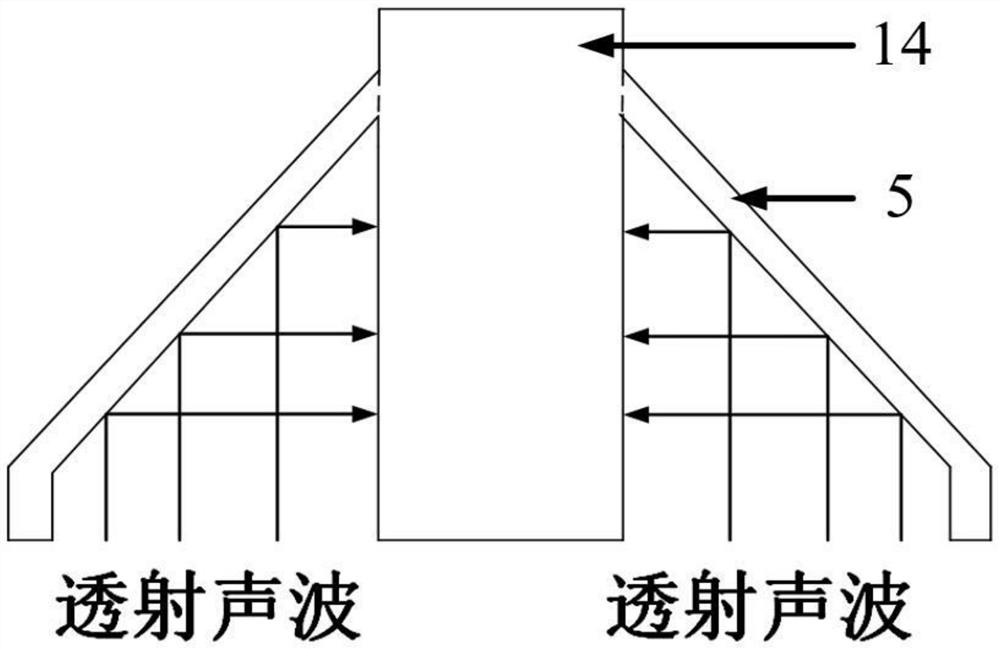
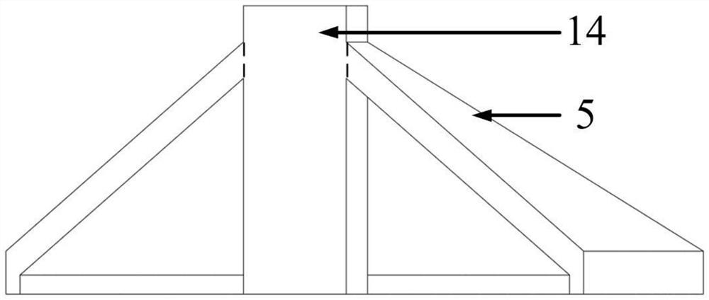
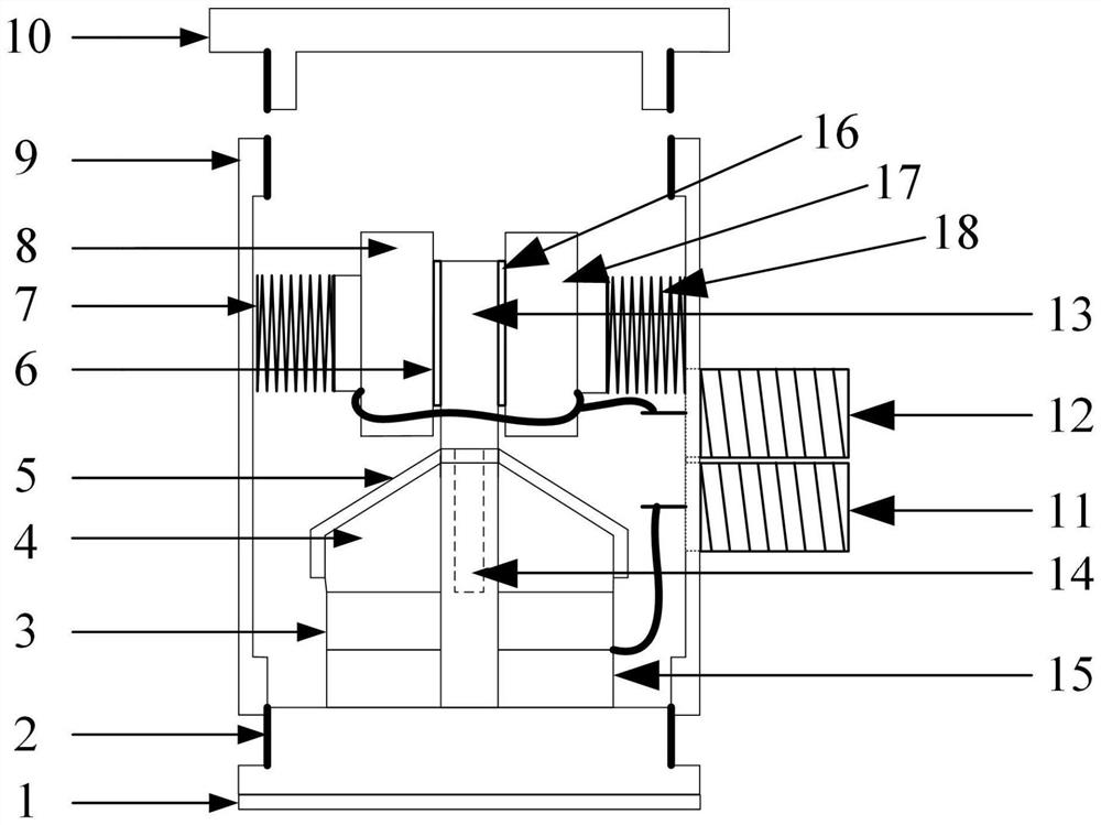
The invention discloses a shear vibration-ultrasonic composite sensor and a measuring device. In the shear vibration-ultrasonic composite sensor, the metal matching layer includes an insulating layer arranged on the lower surface and a support column arranged on the upper surface, and the metal matching layer The object to be measured is contacted through the insulating layer, the first negative electrode surface of the first thick piezoelectric element is attached to the side of the metal matching layer, and the first positive electrode surface of the second thick piezoelectric element is attached to the second positive electrode surface of the second thick piezoelectric element. The two negative electrode surfaces are attached to the first surface of the backing block, and the second surface of the backing block is provided with a metal shell. The first and second anode surfaces of the thick piezoelectric element are connected to the ultrasonic signal output interface to output ultrasonic signals. The vibration base is detachably connected to the support column, the first and second negative surfaces of the first and second tangential piezoelectric elements are attached to one side of the vibration base, and the first and second positive surfaces are respectively attached to the first and second masses. combine. Both the first and second mass blocks are connected to the vibration signal output interface to output the vibration signal.

Description

technical field [0001] The invention relates to the technical field of sensor detection, in particular to a shear vibration-ultrasonic composite sensor and a measuring device. Background technique [0002] With the continuous development of acoustic technology, ultrasonic and vibration detection technology not only exists in traditional industrial and agricultural technology, but also has been integrated into high-tech such as electric power, national defense, biology, medicine and aerospace, especially in the state detection and monitoring of power equipment. widely. When electrical faults occur in power equipment, the deterioration of insulation performance is often accompanied by the occurrence of partial discharge. The ultrasonic signal (frequency higher than 20kHz) caused by partial discharge has strong penetrating power and good directionality in the medium, and it is easy to realize fast and accurate detection. Online and offline non-destructive testing, so ultrasoni...

Claims


Application Information

Patent Timeline
Patent Type & Authority Patents(China)
IPC IPC(8): G01D5/54G01D5/62G01D21/02
CPCG01D5/54G01D5/62G01D21/02G01N29/041G01N29/09G01N29/2437G01N29/28G01N2291/018G01N2291/023G01N29/221
Inventor 李军浩宋颜峰张昭宇
Owner XI AN JIAOTONG UNIV
Learn More