Water returning device with double-S-bend water seal

A water return device and curved water technology, applied in the direction of drying gas arrangement, drying solid materials, non-progressive dryers, etc., can solve the problems of easily damaged joints, low energy utilization rate, high production cost, etc., and reduce maintenance Cost, increase water seal effect, reduce energy consumption effect

Pending Publication Date: 2021-11-16
JIAOZUO ZHENJIENNEG DRYING EQUIP DEV
View PDF0 Cites 0 Cited by
  • Summary
  • Abstract
  • Description
  • Claims
  • Application Information

AI Technical Summary

Problems solved by technology

[0002] Drum drying equipment is one of the important equipment used for drying cigarettes, food, materials, flowers and other materials for many years. The existing drum drying equipment can be divided into two types according to the nature of the drying heat source, namely hot air heat exchange Type dryers and steam heat exchange dryers, hot air heat exchange dryers generally pass hot air directly into the drum as the drying heat source, that is, when the materials are flipped and sprinkled in the drum, they are connected to the drum. The hot air contacts to take away the moisture to achieve drying. Since the drying equipment is in a state of feeding and discharging, during the drying process, most of the heat of the hot air may be lost before being used. Energy utilization The efficiency is low, because the shortcomings of the hot air heat exchange dryer are more prominent, which then promotes the birth of the steam heat exchange dryer. The steam heat exchange dryer is covered with heat dissipation pipes on the inner wall of the drum, and through Into the hot steam, the material is turned and sprinkled in the drum and at the same time it is in contact with the heat dissipation pipe to achieve drying. However, the steam in the heat dissipation pipe will become water vapor after heat exchange and needs to be discharged in time. Usually, a rotary joint installed coaxially with the drum is used. The connecting pipe is directly welded between the rotating joint and the cooling pipe on the inner wall of the drum. Firstly, there will be a slight relative movement between the rotating joint and the rotating joint during the rotation of the drum, which causes the above connecting pipe to be continuously rubbed under the action of alternating stress. The joints at both ends are easily damaged. Moreover, if the connecting pipe is directly connected to the outside world through a rotary joint, it is easy to discharge the steam that has not been used in the heat dissipation pipe together with the condensed water, which leads to a large waste of energy and high production costs.

Method used


Image

  • Water returning device with double-S-bend water seal
  • Water returning device with double-S-bend water seal
  • Water returning device with double-S-bend water seal

Examples


Embodiment 1

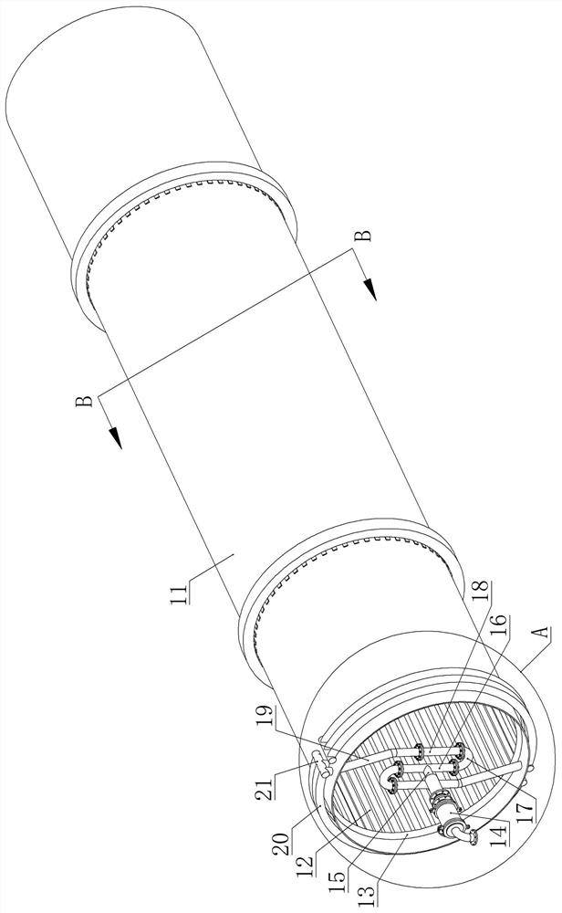
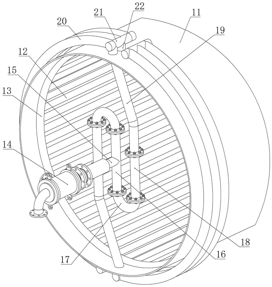
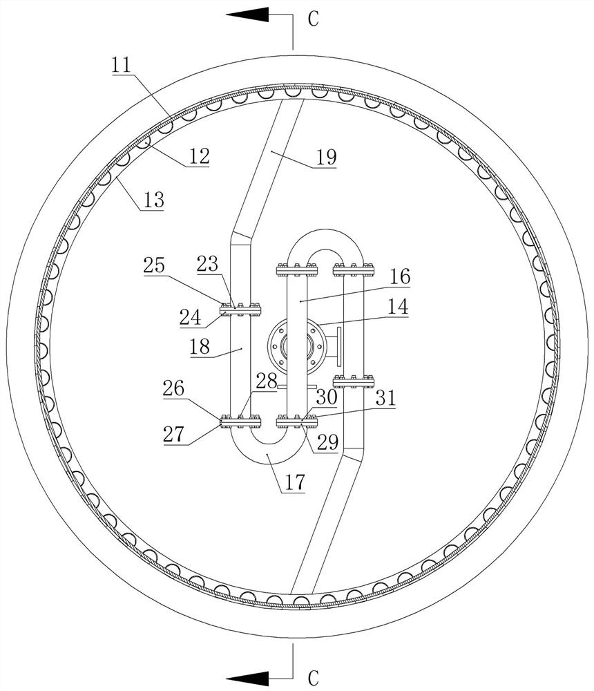
[0025] Example 1, see Figure 1-8 The returning device with double S bending water seal, the device is mounted on the end of the drum including a rotary joint, a returning pipe group mounted between the rotary joint and the drum;

[0026] The returning pipe group includes a split tube, a flexible steam catheter, and a U-water seal, which is disposed at one end of the drum coaxial, and the inner end seal of the exhaust pipe on the rotary joint is fixed. The middle stage of the dispensing tube, and the above-described exhaust pipe is connected to the distribution tube, and the U-type water sealing tube in which it is internally communicated with the dispensing pipe is sealed, and the free end of each U-water seal tube is sealed. The flexible steam catheter is fixed to its internal communication, the free end seal of the flexible steam catheter fixes a split tube in which the internal communication thereof is fixed, and the free end seal of the transfer tube is fixed to the first gene...


PUM


Abstract

The invention relates to a water returning device with a double-S-bend water seal. The device is mounted at the end of a roller and comprises a rotating connector and a water returning pipe group mounted between the rotating connector and the roller, wherein the water returning pipe group comprises adapting pipes, flexible steam guide pipes and U-shaped water seal pipes which are sequentially communicated with each other; the rotating connector is coaxially arranged at one end of the roller; the inner end of an exhaust pipe on the rotating connector is vertically communicated with a middle section of a distribution pipe in a sealing mode; U-shaped water seal pipes communicated with the interior of the distribution pipe are fixed on two ends of the distribution pipe in a sealing mode; a flexible steam guide pipe communicated with the interior of each U-shaped water seal pipe is fixed on the free end of the U-shaped water seal pipe in a sealing mode; an adapting pipe communicated with the interior of each flexible steam guide pipe is fixed on the free end of the flexible steam guide pipe in a sealing mode; and the free ends of the adapting pipes are fixed on a first collecting pipe communicated with the interiors of the adapting pipes in a sealing mode. The water returning device is reasonable in structure and convenient to mount; and the waste amount of the steam is reduced through the water sealing effects of the U-shaped water seal pipes in a condensate water discharging process.

Description

Technical field [0001] The present invention relates to the technical field of dryer equipment, and more particularly to a backwater device with double S curved water seal. Background technique [0002] The drum drying equipment is one of the years for drying in the cigarette, food, materials, flowers and other materials. Existing drum drying equipment can be divided into two types according to their drying heat source, that is, hot fluid-exchanged heat The type dryer and steam heat transfer dryer, hot air heat transfer dryer generally pass through the heat air directly into the drum as drying heat sources, is to flipping through the material in the roller and turning The hot air contact with water is taken to dry. Since the drying equipment is in a state of the feed and discharge, the heat of the hot air may not be used in the process of drying, and the energy utilization Low rate, due to the shortcomings of hot air-switched heat-cutting dryers, thereby promoting the birth of th...

Claims


Application Information

Patent Timeline
IPC IPC(8): F26B11/04F26B21/08F26B25/00F28B9/08
CPCF26B11/04F26B21/005F26B21/08F26B25/00F28B9/08
Inventor 岳正喜岳斌斌石芳芳岳生文
Owner JIAOZUO ZHENJIENNEG DRYING EQUIP DEV
Why Eureka
Try Eureka