
Energy collector

An energy harvester and vibration energy technology, applied in the direction of electrical components, electromechanical devices, etc., can solve the problems of low output voltage, complex processing and assembly, etc., and achieve the effects of high output voltage, reliable electrical connection, and increased output voltage

Active Publication Date: 2021-12-21
QUJING NORMAL UNIV
View PDF5 Cites 0 Cited by
  • Summary
  • Abstract
  • Description
  • Claims
  • Application Information

AI Technical Summary

Problems solved by technology

It solves the problems of complex processing and assembly and low output voltage of the existing energy harvester

Method used


Image

  • Energy collector
  • Energy collector
  • Energy collector

Examples


Embodiment

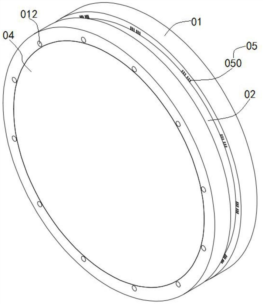
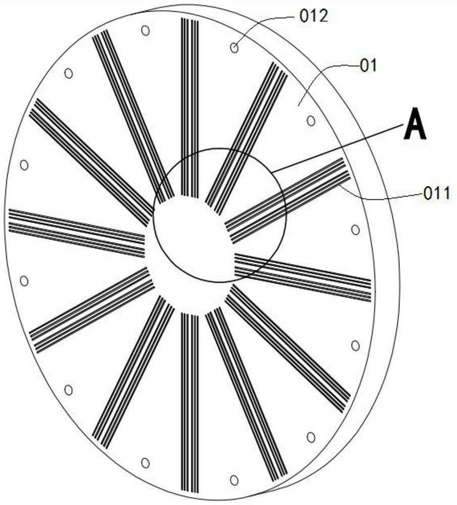
[0037] See attached Figure 1-8 It is a schematic diagram of the overall and partial structure of an embodiment of the present invention. The present invention specifically discloses an energy harvester that is electrically connected to an external load and converts environmental vibration energy into electrical energy, including:

[0038] Cover plate 01, there are two cover plates 01 arranged opposite to each other;

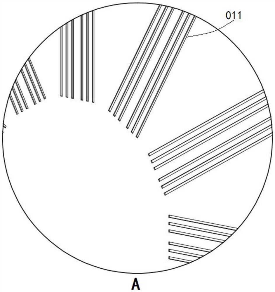
[0039] Limiting plate 02, the limiting plate 02 is arranged parallel to the cover plate 01 and it is located between the two cover plates 01, and there are a plurality of elongated limiting through holes 020 radially distributed on the limiting plate 02, the limiting The two sides of the plate 02 are in sealing contact with the plate surface of the cover plate 01 respectively, and the position corresponding to the limit through hole 020 forms an accommodation chamber, and the interior of the accommodation chamber is partially filled with room temperature liquid ...


PUM


Abstract

The invention discloses an energy collector, and the energy collector comprises two cover plates which are oppositely arranged; a limiting plate located between the two cover plates, wherein a plurality of limiting through holes are evenly distributed in the plate face of the limiting plate and filled with normal-temperature liquid metal; magnetic plates embedded in the cover plates; and a wire set composed of one or more wires, wherein the wires located on the two cover plates are conducted through normal-temperature liquid metal, the wires located on the two cover plates can lead out one or more connecting ends at will to be communicated with one or more input ends of a load, and the ends, connected with an external load, of the wires can be communicated with one another to form a closed coil. According to the invention, the normal-temperature liquid metal with good fluidity is applied to the energy collector, so that the energy collector can receive very tiny vibration and effectively convert the vibration into electromotive force; and by arranging the cover plates and the limiting plate, the normal-temperature liquid metal can be effectively sealed and stored in the limiting through holes.

Description

technical field [0001] The invention relates to the field of energy harvesting, and more specifically relates to an energy harvester. Background technique [0002] With the continuous development of micro-electro-mechanical system technology, the technical level and application range of micro-electro-mechanical devices such as various micro-electronic devices, micro-sensors, and portable electronic devices continue to expand, and they have broad application prospects in various military and civilian fields. [0003] Vibration is the most common and widespread form of energy. Using Faraday's law of electromagnetic induction to collect vibration energy through energy harvesting technology and convert it into electrical energy for storage and use is currently a relatively mature way in the world. [0004] The traditional electromagnetic energy harvester adopts the design method of moving iron, moving coil or iron ring to vibrate at the same time. According to the current resear...

Claims


Application Information

Patent Timeline
Patent Type & Authority Applications(China)
IPC IPC(8): H02K44/08
CPCH02K44/085
Inventor 陈文国
Owner QUJING NORMAL UNIV
Learn More