
Solid gravity flow carrying equipment, gravity energy storage elements and energy storage system

A technology for energy storage components and energy storage systems, which is applied to systems, electrical components, and mechanical equipment for storing electrical energy, and can solve the problems of poor applicability and high terrain requirements.

Pending Publication Date: 2021-11-16
吴炎喜
View PDF0 Cites 8 Cited by
  • Summary
  • Abstract
  • Description
  • Claims
  • Application Information

AI Technical Summary

Problems solved by technology

[0006] In view of the above-mentioned deficiencies in the prior art, the object of the present invention is to provide a solid gravity flow carrying device, a gravity energy storage element and an energy storage system to solve the problems of high terrain requirements and poor applicability in the prior art

Method used


Image

  • Solid gravity flow carrying equipment, gravity energy storage elements and energy storage system
  • Solid gravity flow carrying equipment, gravity energy storage elements and energy storage system
  • Solid gravity flow carrying equipment, gravity energy storage elements and energy storage system

Examples


Embodiment 1

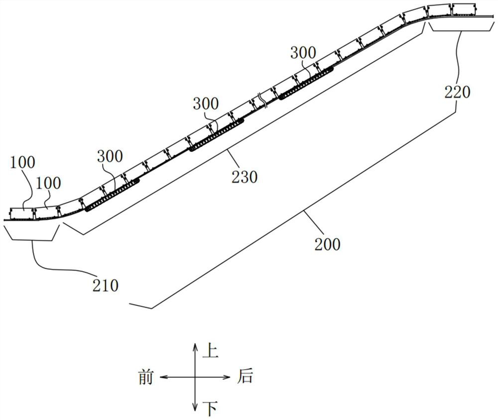
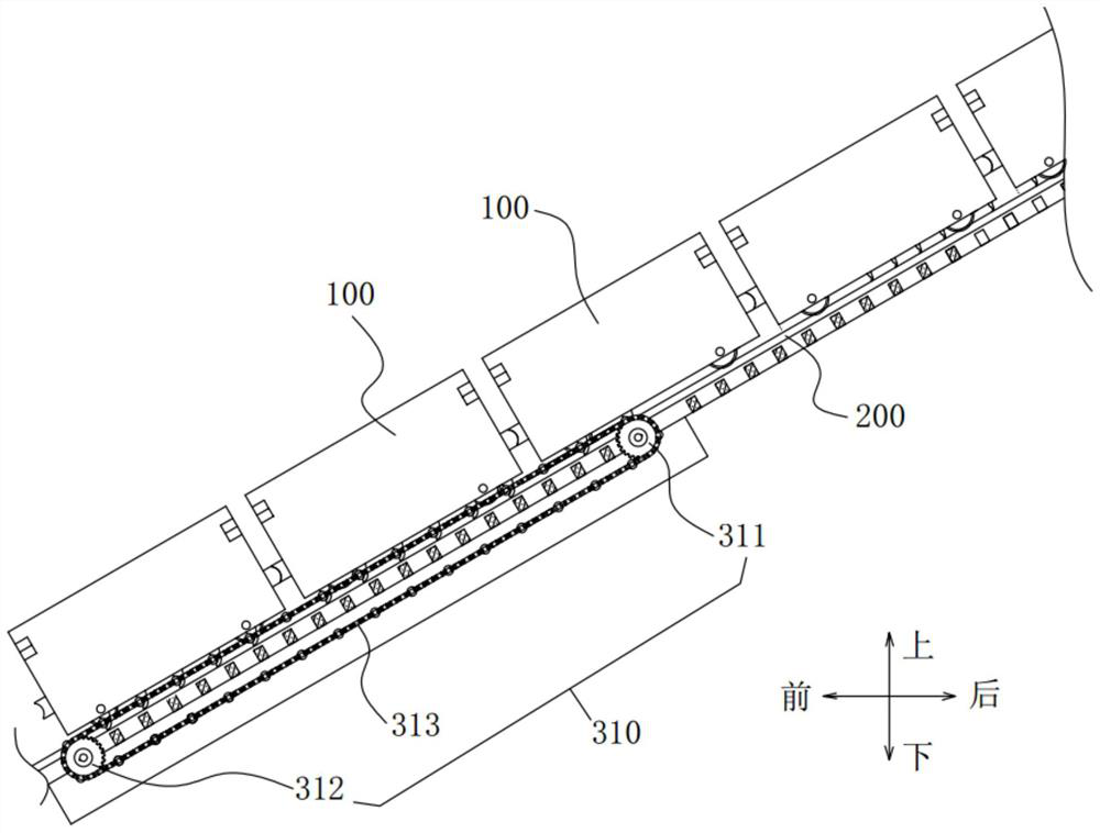
[0059] Example as figure 1 , image 3 As shown, this embodiment proposes a solid gravity flow carrying device for transferring the gravitational energy storage element 100 , which includes: a transfer track 200 , a pushing mechanism 300 , and an electric energy-kinetic energy conversion mechanism 400 . The transfer track 200 has a low-altitude section 210 and a high-altitude section 220 opposite to the low-altitude section 210, and an inclined section 230 between the low-altitude section 210 and the high-altitude section 220, wherein the low-altitude section 210 and the high-altitude section 220 are horizontal sections. For example, when the equipment is installed on a mountain, a flat ground is provided at the foot of the mountain for setting the low-altitude section 210 of the transfer track 200 . A flat ground is set on the top of the mountain or on the mountainside for setting the high-altitude section 220 of the transfer track 200 . The inclined section 230 of the tran...

Embodiment 2

[0070] Such as Figure 8 , Figure 9 As shown, based on the same concept, on the basis of the first embodiment, the present invention also proposes a gravity energy storage element 100, which is used for the solid gravity flow carrying device as described above; the gravity energy storage element 100 and the The force transmission member 320 is used in conjunction with the gravitational energy storage element 100 including an energy storage element body 110 and a track wheel 120 . The track wheel 120 is rotatably disposed on the energy storage element body 110 and moves against the transfer track 200 . There are a plurality of track wheels 120, and the plurality of track wheels 120 respectively lean against the transfer track 200 on both sides. In this way, the energy storage element body 110 is supported by the track wheels 120 , and the friction force of the energy storage element body 110 on the transfer track 200 is reduced, so that the energy storage element body 110 ca...

Embodiment 3

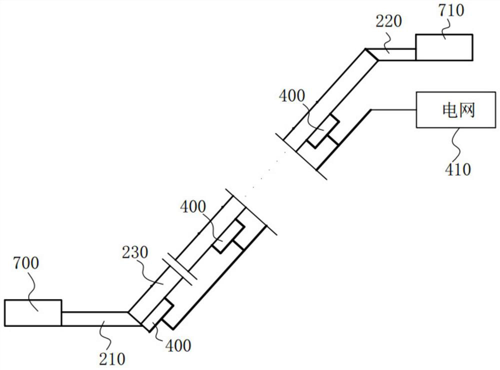
[0080] Such as Figure 10 As shown, based on the same concept, on the basis of Embodiment 1 or Embodiment 2, the present invention also proposes an energy storage system, including the above-mentioned solid gravity flow carrying equipment, and multiple gravity energy storage elements 100, A low-altitude stockyard 700 and a high-altitude stockyard 710; the gravity energy storage element 100 is separated from or connected to the push mechanism 300, the low-altitude section 210 runs through the low-altitude stockyard 700, and the high-altitude section 220 Running through the high-altitude stockyard 710 . When the energy storage system stores energy, the low-altitude stockyard 700 is used to push the gravity energy storage element 100 to the low-altitude section 210, and the high-altitude stockyard 710 is used to push the gravitational energy storage element 100 from the high-altitude section 220 receives and stores the gravitational energy storage element 100 . When the energy ...


PUM


Abstract

The invention discloses solid gravity flow carrying equipment, gravity energy storage elements and an energy storage system. The solid gravity flow carrying equipment comprises a transfer track, wherein the transfer track is provided with a low-altitude section, a high-altitude section opposite to the low-altitude section and an inclined section, and the transfer track is used for enabling the gravity energy storage elements to directionally move; a plurality of pushing mechanisms are arranged side by side along the inclined section of the transfer track; electric and kinetic energy conversion mechanisms are connected with the pushing mechanisms; the plurality of pushing mechanisms are driven by the corresponding electric and kinetic energy conversion mechanisms to move and drive the plurality of gravity energy storage elements to be continuously pushed to the high-altitude section from the low-altitude section along the inclined section; or the plurality of pushing mechanisms move through the gravity action of the plurality of gravity energy storage elements and drive the corresponding electric and kinetic energy conversion mechanisms to convert the mechanical kinetic energy into the electric energy, and the gravity action is formed in the mode that the gravity energy storage elements are continuously pushed from the high-altitude section to the low-altitude section along the inclined section to slide downwards. The problems that in the prior art, the terrain requirement is high, and the applicability is not high are solved.

Description

technical field [0001] The invention relates to the field of gravity energy storage, in particular to a solid gravity flow carrying device, a gravity energy storage element and an energy storage system. Background technique [0002] The use of energy by human society is limited by reserves, and fossil energy such as coal, oil, and natural gas that pollute the environment is used in production and life. It will be a historical necessity to transform the dependence on traditional polluting energy into inexhaustible, clean, environmentally friendly and renewable renewable energy such as solar energy and wind energy. [0003] However, renewable energy has the nature of natural generation, intermittent and random fluctuations, and is an unstable energy source. To transform intermittent and randomly fluctuating unstable energy into smart energy that is supplied on demand, the energy storage link is the key to energy transformation. Energy is the basic material for the operation ...

Claims


Application Information

Patent Timeline
IPC IPC(8): F03G3/00H02J15/00H02J3/28
CPCF03G3/00H02J15/00H02J3/28Y02E60/16
Inventor 吴炎喜
Owner 吴炎喜
Learn More