Automatic plate edge trimming machine for manufacturing children products
A technology of trimming machine and supplies, applied in metal processing and other directions, can solve the problems of inability to stabilize the sheet, time-consuming and laborious trimming, and complicated steps for trimming the sheet.
- Summary
- Abstract
- Description
- Claims
- Application Information
AI Technical Summary
Problems solved by technology
Method used
Image


Examples
Embodiment 1
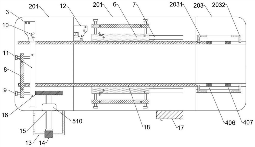
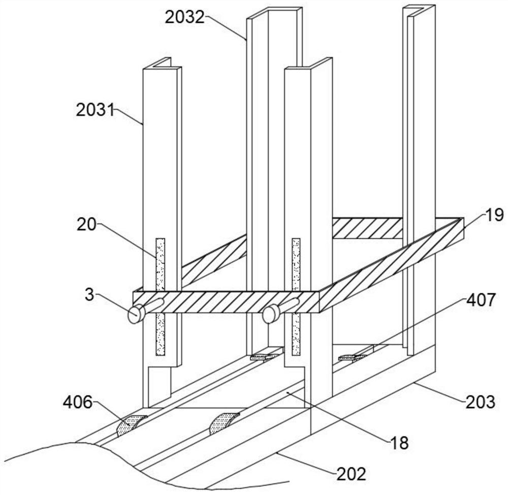
[0033] Such as Figure 1-3 , Figure 6 with Figure 8 As shown, the automatic plate trimming machine for the manufacture of children's products includes a support frame 1, a first workbench 201, a second workbench 202 and a third workbench 203, and the second workbench 202 is installed on the top of the support frame 1 The first workbench 201 and the third workbench 203 are respectively installed on both sides of the second workbench 202, and an operation box 17 is installed on one side of the support frame 1, which is used to control the opening and closing of the whole device. The first workbench 201 1.5cm lower than the level of the second workbench 202, after the trimming of the plate through the second workbench 202, it smoothly moves to the first workbench 201 for trimming on the other two sides. The bottom of the third workbench 203 is installed with The clamping assembly 4 and the feeding assembly 5, the feeding assembly 5 includes a driving motor 501, the output end...
Embodiment 2
[0038] Such as Figure 1-5 and Figure 7 As shown, the clamping assembly 4 includes a first support rod 401, one end of the first support rod 401 is connected with a telescopic rod 402, the other end of the first support rod 401 is fixedly connected with a second push rod 508, and the telescopic rod 402 is far away from the first One end of the support rod 401 is equipped with a second support rod 403, the outer side of the telescopic rod 402 is provided with a spring, and the two ends of the spring are fixedly connected with the first support rod 401 and the second support rod 403 respectively. 401 and the second support rod 403 are relatively moved through the telescopic rod 402 to realize the clamping of different plates through the support column 404. The tops of the first support rod 401 and the second support rod 403 are fixedly connected with the support column 404, and support The column 404 is arranged symmetrically, the top of the support column 404 is fixedly conne...
Embodiment 3
[0041] Such as Figure 1-5 As shown, the top of the second workbench 202 is equipped with a first knife rest 6 through fastening bolts 3, and the first knife rest 6 is symmetrically arranged to realize trimming of the plate, and one end of the first knife rest 6 is installed with a second A guide bar 7, the opposite side of the first knife rest 6 is equipped with a crossbar 8 by fastening bolts 3, the outside of the crossbar 8 is provided with an adjustment bolt 9, and one end of the adjustment bolt 9 is connected to the first knife rest 6 Threaded connection, during specific setting, turn the adjusting bolt 9 to adjust the first knife rest 6, trim the plate, the first knife rest 6 is provided with a first installation groove, and a sharpening knife 10 is installed in the first installation groove by detachable , to facilitate the replacement of the worn sharpener 10, the top of the first workbench 201 is equipped with a second guide rod 11 through the fastening bolt 3, and th...
PUM
 Abstract
Description
Claims
Application Information
 - R&D
- Intellectual Property
- Life Sciences
- Materials
- Tech Scout
- Unparalleled Data Quality
- Higher Quality Content
- 60% Fewer Hallucinations
Browse by: Latest US Patents, China's latest patents, Technical Efficacy Thesaurus, Application Domain, Technology Topic, Popular Technical Reports.
© 2025 PatSnap. All rights reserved.Legal|Privacy policy|Modern Slavery Act Transparency Statement|Sitemap|About US| Contact US: help@patsnap.com