
Pipeline transmission continuous vacuum coating production line structure and production method

A vacuum coating and production line technology, applied in vacuum evaporation coating, sputtering coating, ion implantation coating, etc., can solve the problems of cumbersome time-consuming, low processing efficiency, large resource and labor consumption, etc., to achieve convenient operation, The effect of high utilization rate of equipment and improvement of production efficiency

Pending Publication Date: 2021-11-12
TRITREE METAL SHENZHEN +1
View PDF1 Cites 2 Cited by
  • Summary
  • Abstract
  • Description
  • Claims
  • Application Information

AI Technical Summary

Problems solved by technology

[0004] It should be pointed out that when the vacuum coating technology is used to coat the substrate, in order to achieve the expected coating effect, it is often necessary to coat multi-layer films in stages. The thin film is installed on the workpiece once, and the workpiece is taken out after the coating is completed. After adjusting the expected processing target again, the workpiece is put back to be processed again. Each layer of thin film needs to be processed separately. It is necessary to transfer the workpiece for reprocessing, which not only consumes a lot of resources and labor, but also the whole processing process will be very cumbersome and time-consuming, and the processing efficiency will be very low

Method used


Image

  • Pipeline transmission continuous vacuum coating production line structure and production method
  • Pipeline transmission continuous vacuum coating production line structure and production method
  • Pipeline transmission continuous vacuum coating production line structure and production method

Examples


Embodiment Construction

[0036] In order to make the object, technical solution and advantages of the present invention clearer, the present invention will be further described in detail below in conjunction with the accompanying drawings and embodiments. It should be understood that the specific embodiments described here are only used to explain the present invention, not to limit the present invention.

[0037] To achieve the above object, the technical scheme of the present invention is as follows:

[0038] see Figure 1-6 .

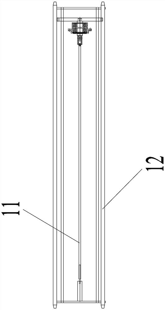
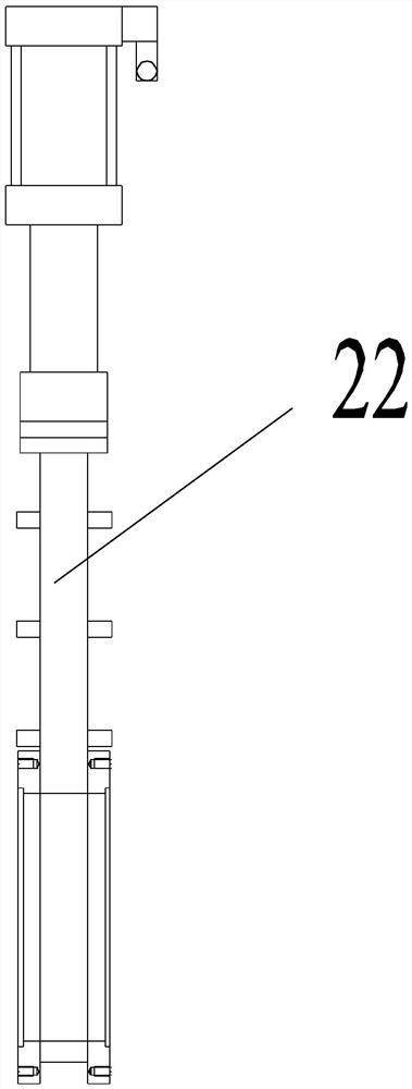
[0039] In this specific embodiment, a pipeline transmission continuous vacuum coating production line structure is provided, the production line structure includes a workpiece frame 1 and processing components 2; at least one of the processing components 2 has an internal processing space for coating processing of workpieces to be processed and at least one isolation valve 22 for isolating or connecting different spaces;

[0040] A plurality of processing tubes 21 are arr...


PUM


Abstract

The invention discloses a pipeline transmission continuous vacuum coating production line structure, and particularly relates to the technical field of vacuum coating equipment. The production line structure comprises a workpiece frame and machining assemblies. At least one of the machining assemblies is provided with machining pipes provided with internal machining spaces and used for coating a to-be-machined workpiece, and at least one isolating valve used for isolating or communicating the different spaces; and the multiple machining pipes are arranged in sequence, the isolating valves are arranged between the adjacent machining pipes, and after the adjacent machining pipes are connected through the isolating valves, the internal machining spaces of the adjacent machining pipes are communicated to form a channel allowing the workpiece frame to be conveyed. The invention further provides a pipeline transmission continuous vacuum coating production method, compared with the prior art, the production line structure has the advantages of being flexible in structure, good in consistency, high in automation degree, high in controllability and the like, and the production method has the beneficial effects of being good in expansibility, convenient to operate, high in coating efficiency, high in device utilization rate and the like.

Description

technical field [0001] The invention belongs to the technical field of vacuum coating equipment, in particular to a coating production line structure. Background technique [0002] Vacuum coating technology uses evaporation, magnetron sputtering, chemical vapor deposition and other methods to form films in a vacuum environment. Compared with traditional wet coating technology, its film and substrate materials are more widely selected, and the film thickness is more controllable. The formed film has better bonding strength with the substrate, and the film forming process does not generate waste liquid, so it gradually replaces the traditional wet coating technology and is widely used in the fields of material surface coating, optical instrument manufacturing, and integrated electronic hardware manufacturing. [0003] Existing vacuum coating equipment using vacuum coating technology often has a fixed equipment structure. Taking the Chinese patent application document with the ...

Claims


Application Information

Patent Timeline
IPC IPC(8): C23C14/56
CPCC23C14/568C23C14/56
Inventor 汪友林
Owner TRITREE METAL SHENZHEN
Learn More