High-speed forming and separating device for automobile plastic part

A separation device and technology for plastic parts, applied in separation methods, separation of dispersed particles, household components, etc., can solve the economic loss of manufacturers, reduce the production efficiency of plastic parts, and the doping of raw material particles, so as to increase processing efficiency and shorten molding Time, the effect of eliminating doping impurities

Inactive Publication Date: 2021-11-12
江苏云端智能科技有限公司
View PDF0 Cites 0 Cited by
  • Summary
  • Abstract
  • Description
  • Claims
  • Application Information

AI Technical Summary

Problems solved by technology

[0002] With the development of society and the continuous improvement of people's living standards, people use cars more and more frequently, which makes the demand for cars increase sharply. Among them, the processing and production efficiency of automotive plastic parts is also in urgent need of improvement, but the existing equipment When producing automotive plastic parts, the plastic parts need to be cooled naturally, which greatly reduces the production efficiency of the plastic parts. At the same time, due to the incomplete melting of the raw materials, the raw material particles are mixed, resulting in large cavities and defects. Other machinery is needed to separate the mold from the plastic part, which prolongs the production time of the plastic part. After a long time of equipment processing, it often causes the mold to be not tightly closed, causing side leakage of the plastic part, causing large burrs, and making the plastic part The quality declines, causing greater economic losses to manufacturers

Method used


Image

  • High-speed forming and separating device for automobile plastic part
  • High-speed forming and separating device for automobile plastic part
  • High-speed forming and separating device for automobile plastic part

Examples


Embodiment 1

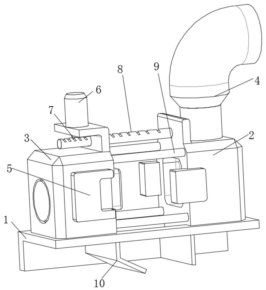
[0026] see Figure 1-Figure 3 , a high-speed molding and separating device for automobile plastic parts, comprising a frame 1, a cooling mechanism 2 is arranged on the top of the frame 1, an ejection mechanism 3 is slidingly connected to the top of the frame 1, and a feeding mechanism 3 is arranged on the top of the ejection mechanism 3 Mechanism 4, the outside of the ejector mechanism 3 is provided with a positioning and fixing mechanism 5, the top of the ejector mechanism 3 is provided with a mold clamping motor 6, the bottom of the mold clamping motor 6 is rotatably connected with an arc gear 7, and the top of the cooling mechanism 2 is provided with A positioning guide post 9 is arranged between the feed rod 8 , the cooling mechanism 2 and the ejection mechanism 3 , and a collecting bin 10 is arranged at the bottom of the frame 1 .

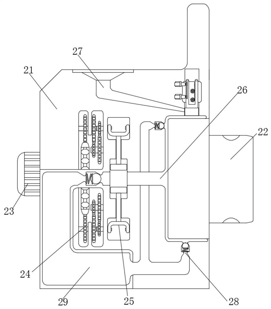
[0027] Cooling mechanism 2 comprises cooling seat 21, and the outside of cooling seat 21 is provided with locating plate 22, and the left sid...

Embodiment 2

[0029] see Figure 4, a high-speed molding and separating device for automotive plastic parts, comprising a feed mechanism 4, the feed mechanism 4 includes a melt rack 41, the inside of the melt rack 41 is provided with an equalizing groove 42, and the inside of the melt rack 41 is rotatably connected with a melting Drum 43 and refinement drum 44, the internal rotation of melting rack 41 is connected with quantitative screw 45, feeding mechanism 4 can transport the granular raw material to the top of melting drum 43 evenly, and the melting drum 43 in the heating state can carry out the process of granular raw material Preliminary melting, and the preliminary melted granular raw material is transported to the refining drum 44, and the refining drum 44 with a higher temperature melts the preliminary melted granular raw material again, and the distance between the refining drums 44 is higher than that between the melting drums 43 The pitch of the granular raw material is smaller....

Embodiment 3

[0031] see Figure 5 , a high-speed molding and separating device for automobile plastic parts, the ejector mechanism 3 includes an ejector seat 31, a filter screen 32 is arranged on the right side of the ejector seat 31, a powerful fan 33 is arranged inside the ejector seat 31, and the ejector seat 31 The inside of the ejector frame 34 is slidingly connected with an ejector frame 34, and the inner part of the ejector frame 34 is rotatably connected with a conical top block 35, and the outer side of the ejector frame 34 is sleeved with a return spring 36, and the ejector mechanism 3 can make the molded plastic parts and The mold provided on the left side of the ejector seat 31 is separated, and the plastic part is separated from the mold after the injection molding is completed, so as to ensure the smooth completion of the subsequent mold closing and injection molding of the next plastic part, which greatly saves the processing time and reduces the need for plastic removal. It...


PUM


Abstract

The invention relates to the technical field of automobile plastic part forming, and discloses a high-speed forming and separating device for an automobile plastic part, which comprises a rack; a cooling mechanism is arranged at the top of the rack; and an ejection mechanism is slidably connected to the top of the rack. According to the high-speed forming and separating device for the automobile plastic part, a cooling motor drives a pressurizing gear to rotate; the pressurizing gear drives a pressurizing piston to move; the pressurizing piston drives cooling liquid in a cooling liquid pool to enter a cooling pipe through the cooling pipe; the plastic part is cooled at a high speed, so that the plastic part is rapidly formed; the used cooling liquid returns to the cooling liquid pool through a one-way valve to be cooled; a circulating gear is driven by a detector to rotate; the circulating gear drives a blocking plate to move; the blocking plate drives a blocking guide column to move to control a feeding port, so that rapid cooling forming is achieved; the forming time of the plastic part is greatly shortened; and the machining efficiency of the plastic part is improved.

Description

technical field [0001] The invention relates to the technical field of forming automobile plastic parts, in particular to a high-speed forming and separating device for automobile plastic parts. Background technique [0002] With the development of society and the continuous improvement of people's living standards, people use cars more and more frequently, which makes the demand for cars increase sharply. Among them, the processing and production efficiency of automotive plastic parts is also in urgent need of improvement, but the existing equipment When producing automotive plastic parts, the plastic parts need to be cooled naturally, which greatly reduces the production efficiency of the plastic parts. At the same time, due to the incomplete melting of the raw materials, the raw material particles are mixed, resulting in large cavities and defects. Other machinery is needed to separate the mold from the plastic part, which prolongs the production time of the plastic part....

Claims


Application Information

Patent Timeline
Patent Type & Authority Applications(China)
IPC IPC(8): B29C45/26B29C45/40B29C45/73B29C45/66B01D46/10B29C45/46B29L31/30
CPCB29C45/26B29C45/4005B29C45/73B29C45/66B01D46/10B29C45/46B29L2031/30
Inventor 刘东方
Owner 江苏云端智能科技有限公司
Why Eureka
Try Eureka