
Auxiliary scrap collecting device of steel machining equipment

A processing equipment and collection device technology, which is applied in the field of steel and aluminum, can solve the problems of steel waste collection, steel waste scattered on the surface of the equipment, and the equipment cannot be kept clean all the time, so as to facilitate recycling and save storage space Effect

Inactive Publication Date: 2021-11-12
黄正化
View PDF0 Cites 0 Cited by
  • Summary
  • Abstract
  • Description
  • Claims
  • Application Information

AI Technical Summary

Problems solved by technology

[0005] Aiming at the deficiencies of the prior art, the present invention provides an auxiliary waste collection device for steel processing equipment, which has the advantages of assisting the operator in collecting steel processing waste in a concentrated manner, compressing the steel processing waste for recycling and saving storage space, and solving the problem of In the process of cutting, grinding, drilling and other processing of steel, there will be more steel waste chips. The existing equipment for processing steel has no way to collect steel waste chips, so that steel waste chips are scattered on the surface of the equipment , so that the equipment cannot be kept clean all the time, if the steel waste falls into the equipment, it will also cause damage to the processing equipment, and for the steel waste, it is a recyclable and reused material, which cannot be realized by the existing steel processing equipment Problems with the function of recycling steel waste

Method used


Image

  • Auxiliary scrap collecting device of steel machining equipment
  • Auxiliary scrap collecting device of steel machining equipment
  • Auxiliary scrap collecting device of steel machining equipment

Examples


Embodiment 1

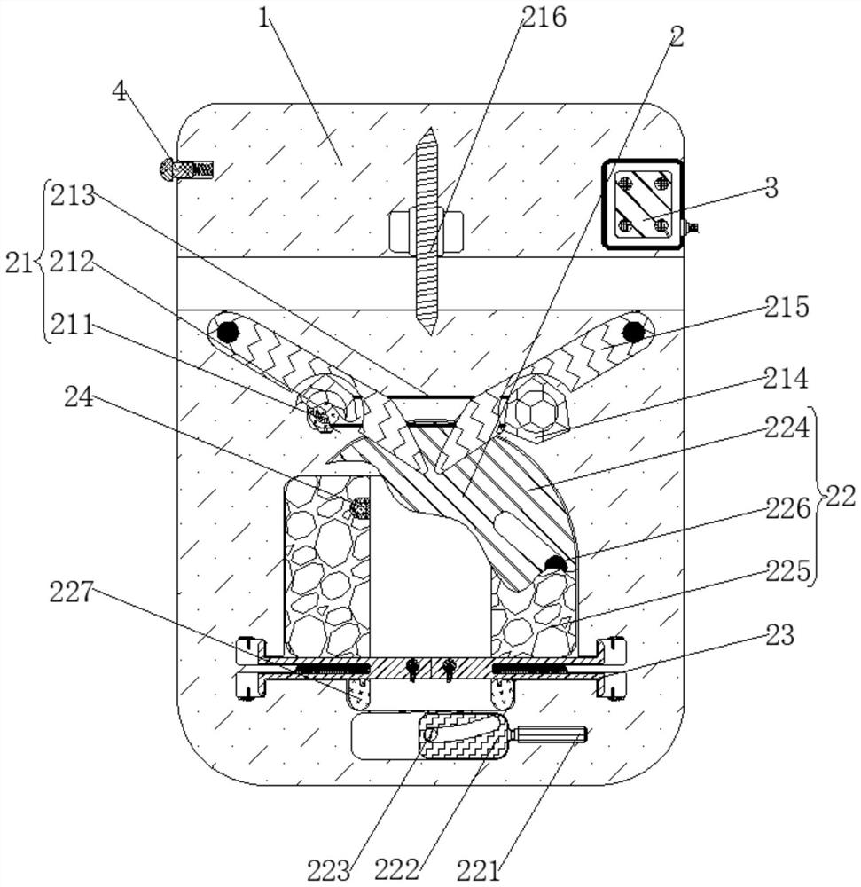
[0026] see figure 1 , an auxiliary waste collection device for steel processing equipment, comprising a casing 1, a collection and compression mechanism 2 is arranged inside the casing 1, and the collection and compression mechanism 2 includes a vibrating assembly 21, a compression assembly 22, a discharge assembly 23, a trigger assembly 24, and the casing 1 is provided with a vibrating assembly 21 for collecting waste. The vibrating assembly 21 includes a motor 211, a transmission wheel 212, a transmission belt 213, a hexagonal block 214, a vibrating plate 215, and a cutting wheel 216. The inside of the housing 1 is fixedly connected with a motor 211. The drive wheel 212 is fixedly connected to the outside of the motor 211, the drive belt 213 is drive connected to the outside of the drive wheel 212, the hexagonal block 214 is fixedly connected to the outside of the drive wheel 212, and the vibrating plate 215 is rotatably connected to the inside of the housing 1. The vibrating...

Embodiment 2

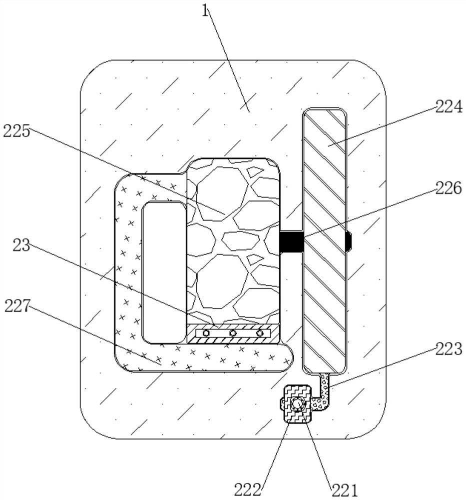
[0029] see Figure 2-4 , an auxiliary waste collection device for steel processing equipment, comprising a casing 1, a collection and compression mechanism 2 is arranged inside the casing 1, and the collection and compression mechanism 2 includes a vibrating assembly 21, a compression assembly 22, a discharge assembly 23, a trigger assembly 24, and the casing 1 is provided with a vibrating assembly 21 for collecting waste, and the interior of the housing 1 is provided with a compression assembly 22 for compressing waste. Compression plate 225, connecting column 226, curved rod 227, the inside of shell 1 is fixedly connected with electric telescopic rod 221, and sliding rod 222 is fixedly connected with the outside of electric telescopic rod 221, and connecting rod 223 is movably connected with the outside of sliding rod 222, rotates The ring 224 is fixedly connected to the outside of the connecting rod 223, the compression plate 225 is slidably connected to the inside of the s...

Embodiment 3

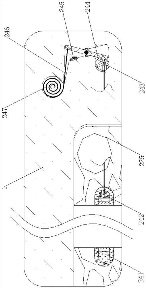
[0033] see Figure 1-4 , an auxiliary waste collection device for steel processing equipment, comprising a casing 1, a collection and compression mechanism 2 is arranged inside the casing 1, and the collection and compression mechanism 2 includes a vibrating assembly 21, a compression assembly 22, a discharge assembly 23, a trigger assembly 24, and the casing 1 is provided with a vibrating assembly 21 for collecting waste. The vibrating assembly 21 includes a motor 211, a transmission wheel 212, a transmission belt 213, a hexagonal block 214, a vibrating plate 215, and a cutting wheel 216. The inside of the housing 1 is fixedly connected with a motor 211. The drive wheel 212 is fixedly connected to the outside of the motor 211, the drive belt 213 is drive connected to the outside of the drive wheel 212, the hexagonal block 214 is fixedly connected to the outside of the drive wheel 212, and the vibrating plate 215 is rotatably connected to the inside of the housing 1. The vibrat...


PUM


Abstract

The invention relates to the technical field of steel and aluminum products, and discloses an auxiliary scrap collecting device of steel machining equipment. The auxiliary scrap collecting device comprises a shell, a collecting and compressing mechanism is arranged inside the shell, the collecting and compressing mechanism comprises a vibration assembly, a compressing assembly, a discharging assembly and a triggering assembly, the vibration assembly for collecting scraps is arranged inside the shell, the compressing assembly for compressing the size of the scraps is arranged inside the shell, the discharging assembly for discharging the compressed scraps is arranged outside the compression assembly, and a triggering assembly for triggering the compression assembly to operate is arranged inside the shell. A rotating ring rotates to drive a connecting column and the compression plate fixedly connected to the connecting column to move, a compression plate moves to compress the machining scraps, the effects that the steel machining scraps are compressed, recycling is convenient, and the storage space is saved can be achieved, the steel scraps can be further recycled, and meanwhile, the device better conforms to the technical concept of intelligent manufacturing.

Description

technical field [0001] The invention relates to the technical field of steel and aluminum materials, in particular to an auxiliary waste collection device for steel processing equipment. Background technique [0002] Modern ordinary steel is mostly supplied in the form of strips, profiles, and wires. Ordinary steel is the earliest and most used basic material in industry, and is widely used in various fields such as building structures, hull structures, and machinery manufacturing. [0003] To process steel into the shape we need, we often need to let the steel go through cutting, grinding, drilling and other processing processes to get the shape of the steel we want. During the process of cutting, grinding, drilling and other processing of steel, There will be more steel waste. The existing steel processing device has no way to collect the steel waste, so that the steel waste is scattered on the surface of the equipment, making the equipment unable to keep clean all the tim...

Claims


Application Information

Patent Timeline
Patent Type & Authority Applications(China)
IPC IPC(8): B23Q11/00B23Q17/24B30B9/32B23D19/00B23D33/00
CPCB23Q11/00B23Q11/0042B23Q17/24B23D19/00B23D33/00B30B9/32B30B9/327
Inventor 黄正化陈慧约
Owner 黄正化
Learn More