Multi-optical path optical axis automatic coaxial laser communication ground terminal and coaxial control method
A laser communication and ground terminal technology, which is applied in the ground terminal field of satellite-to-earth laser communication, can solve the problems of limited control performance, heavy ground terminal weight, and high cost, and achieve the goals of reducing manufacturing costs, high stability, and improving use efficiency Effect
- Summary
- Abstract
- Description
- Claims
- Application Information
AI Technical Summary
Problems solved by technology
Method used
Image
Examples
Embodiment 1
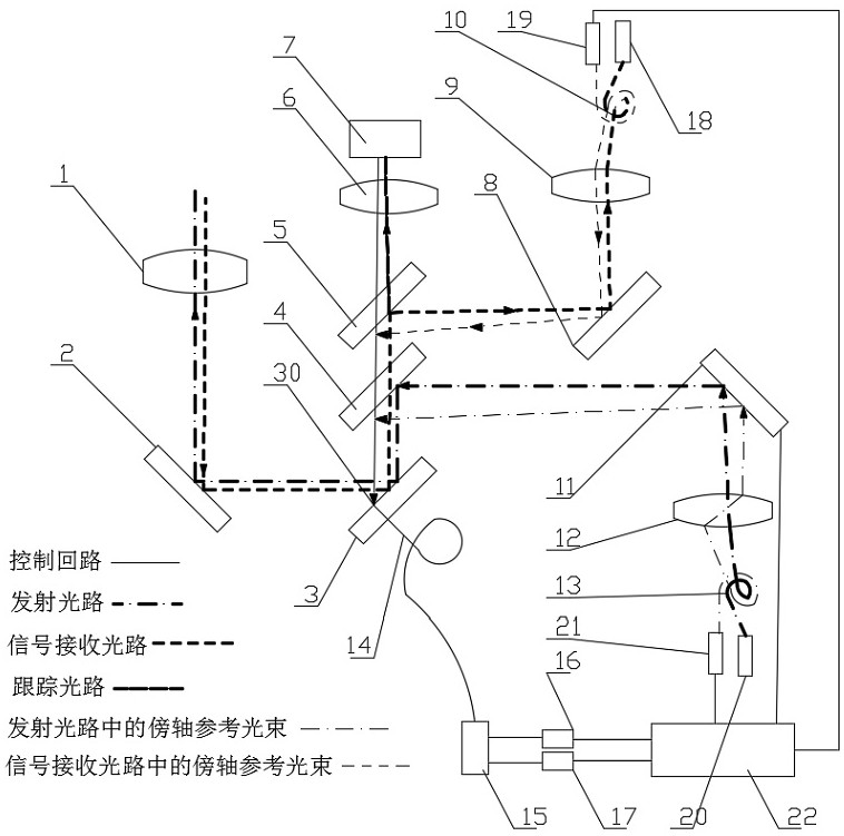
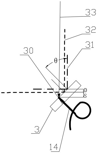
[0040] like Figure 1-2 , The multi-axis light path coaxially with automatic ground terminal laser communication according to the present embodiment, the telescope by the transceivers 1, a tilt mirror 2, folding plane mirror 3, a beam splitter 4, two beam splitter 5, the tracking lens 6 tracking detector 7, two tilt mirror 8, the lens 9 receiving the signal, the signal receiving fiber bundle 10, the received signal detector 18, three tilt mirror 11, emission lens 12, a transmit optical fiber bundle 13, emitting laser 20, reference fiber 14, fiber splitter 15, a photodetector 16, a laser reference beam 17, two reference light laser 19, three laser reference beam 21, the controller 22 components. The above-described components emit light path, the received signal light path, the tracking light path, and in order for the optical axis three-way light path coaxially of control, in the laser communication terminal, increasing the paraxial beams with a small angular difference between the...
Embodiment 2
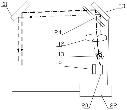
[0055] like image 3 As shown, the present embodiment differs from the first embodiment in that the transmitted optical path in the present embodiment is designed as a transmitted optical path with advance aiming function, by increasing the advance sight 23 and a die-mirror 24 in front of the optical path; The color mirror 24 is located in front of the advance sight 23 and both close to parallel. The reference beam is different from the wavelength of the working beam, and the reference beam is reflected by the die-mirror, while the working beam (i.e., the emitted beam) is reflected by the advance sight 23, and again transmits the color reflection again. Mirror 24. The advance sight 23 can realize independent control of the transmitted beam without affecting the reference beam, in order to achieve an angle difference between the emitted beam relative to the ground terminal. Among them, the beam is not limited by combining the dichroic mirror 24 and the advance sight 23 and the order...
Embodiment 3
[0057] like Figure 4 As shown, the present embodiment differs from the second embodiment in that since the reference beam and the polarization of the emitted beam are different, the polarization beam plate 25 is used instead of the dichroic beam mirror 24 such that the reference beam is polarized. The beam plate 25 is reflected, and the emitted beam has passed through the polarization beam plate 25, and then reflected by the advance sight 23, and then transmitted by the polarization beam plate 25.
PUM
 Abstract
Description
Claims
Application Information
 - R&D
- Intellectual Property
- Life Sciences
- Materials
- Tech Scout
- Unparalleled Data Quality
- Higher Quality Content
- 60% Fewer Hallucinations
Browse by: Latest US Patents, China's latest patents, Technical Efficacy Thesaurus, Application Domain, Technology Topic, Popular Technical Reports.
© 2025 PatSnap. All rights reserved.Legal|Privacy policy|Modern Slavery Act Transparency Statement|Sitemap|About US| Contact US: help@patsnap.com


