
Electroluminescent laser display and construction method thereof

An electroluminescent material and luminescent technology, applied in the direction of electric solid-state devices, circuits, electrical components, etc., can solve the problems of structural compatibility and complex preparation technology, and achieve easy-to-mix laser output, excellent material compatibility, and excellent flow performance effect

Active Publication Date: 2021-11-09
INST OF CHEM CHINESE ACAD OF SCI
View PDF5 Cites 1 Cited by
  • Summary
  • Abstract
  • Description
  • Claims
  • Application Information

AI Technical Summary

Problems solved by technology

However, it is still a great challenge to realize laser display on these display devices due to the problems of structural compatibility of devices and complex fabrication techniques.

Method used


Image

  • Electroluminescent laser display and construction method thereof
  • Electroluminescent laser display and construction method thereof
  • Electroluminescent laser display and construction method thereof

Examples


Embodiment 1-3

[0080] The electroluminescence laser display panel, the panel including a periodically arranged pixel array, the pixel array electroluminescence laser display panel includes a polymer micromotoischarge as a blank pixel, and an electroluminated micromaine in a spin-coated injection polymer micromotactic structure.

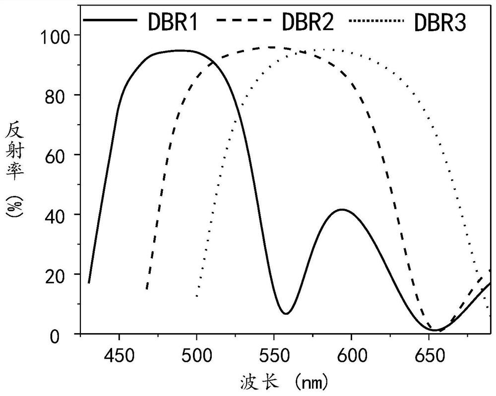
[0081] figure 1 The nature of the distributed Prague mirror used. The ITO-based distributed Prague mirror with high reflectance in the blue zone is DBR1; the ITO-based distributed Prague mirror having high reflectivity in the green spot is DBR2; distribution of ITO based on the red light region The Prague mirror is DBR3. like figure 1 As shown, DBR1, DBR2, and DBR3 have different reflection spectrum, spanning the entire visible region. This facilitates the realization of high-color purity light exits, thereby providing a basis for realizing laser display.

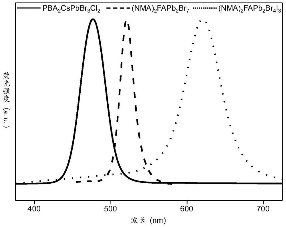
[0082] figure 2 The properties of the perovskite materials used. From figure 2 As can be seen, the fluorescence ...


PUM

PropertyMeasurementUnit
diameteraaaaaaaaaa
thicknessaaaaaaaaaa
thicknessaaaaaaaaaa

Abstract

The invention discloses an electroluminescent laser display and a construction method thereof. According to the electroluminescent laser display, the display comprises a pixel array which is arranged periodically, and the pixel array comprises a polymer micro-template and an electroluminescent micro-structure; the polymer micro-template is used as a blank pixel, and the electroluminescent micro-structure is located in the polymer micro-template; and the electroluminescent micro-structure comprises an electroluminescent material. Through the combination of the electroluminescent micro-structure and a reflection cavity composed of a high-reflection metal electrode and an ITO-based distributed Bragg reflector, high-purity electroluminescence can be formed, and wide-color-gamut and high-saturation color display can be achieved.

Description

Technical field [0001] The present invention belongs to the field of laser display, and more particularly to an electroluminescence laser display and a construction method thereof. Background technique [0002] Laser display, utilizing high monochrome and high brightness of laser emissions, due to its enabled width, high color saturation and high color contrast, have become revolutionary in the display industry Significance technology. Laser display technology is hindered by the application on portable display devices because it lacks electric pump material capable of covering visible light. Therefore, it is of great significance to develop a pixelated display panel having a laser monochrome and color gamut covered by electroluminescence. An effective strategy is to modulate the emission light of the light-emitting diode of the pixel. So far, the display panel of the light-emitting diode as a pixel point has been widely used, such as mobile phones, computers, television, and so o...

Claims


Application Information

Patent Timeline
Patent Type & Authority Applications(China)
IPC IPC(8): H01L51/52H01L51/56H01L27/32
CPCH10K59/353H10K59/10H10K50/818H10K50/852H10K71/00Y02E10/549
Inventor 杜宇翔赵永生
Owner INST OF CHEM CHINESE ACAD OF SCI
Learn More