Heat dissipation cover plate and chip
A heat dissipation cover and chip technology, applied in the direction of electrical components, electric solid devices, circuits, etc., can solve the problems of long heat dissipation channel path and poor heat dissipation effect, and achieve the effect of enhanced heat dissipation effect, increased quantity, and reduced junction temperature
- Summary
- Abstract
- Description
- Claims
- Application Information
AI Technical Summary
Problems solved by technology
Method used
Image


Examples
Embodiment 1
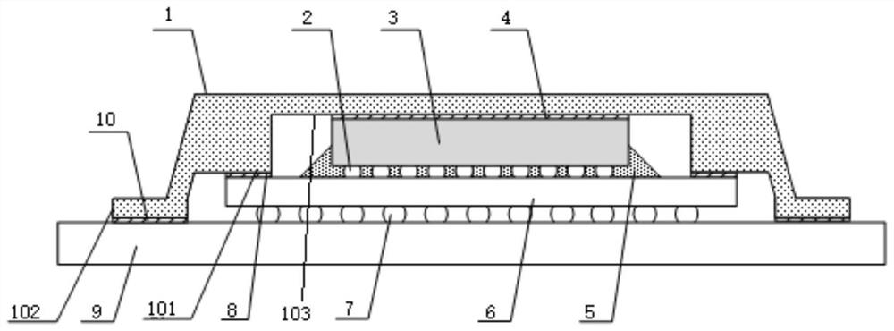
[0046] see image 3 , a chip in this embodiment, which includes a chip body 3, a PCB board 9 and a heat dissipation cover, the chip body 3 is placed on the upper surface of the PCB 9, and the heat dissipation cover includes a cover body 1, which is arranged at the bottom of the heat dissipation body 1 There is a groove, and an accommodating groove is formed between the groove and the PCB board 9; the chip body 3 is arranged in the accommodating groove, and the chip body 3 is in contact with the cover body 1; the bottom end surface of the cover body 1 is in contact with the PCB board 9 The upper end surface of the chip body contacts and forms a second heat dissipation surface 102, and the second heat dissipation surface 102 is used to transfer the heat generated by the chip body 3 to the PCB board 9, that is, between the chip body 3-the second heat dissipation surface 102-the PCB board 9 A heat dissipation channel is formed; wherein, the width of the second heat dissipation sur...
Embodiment 2
[0071] see Figure 4 , a chip in this embodiment. The difference from Embodiment 1 is that the width of the first heat dissipation surface 101 in this embodiment is 4mm; the width of the second heat dissipation surface 102 is 10mm; the third heat dissipation surface 103 is connected to the chip body The contact area between the back surfaces of 3 is the same as the area of the back surface of the chip body 3 .
[0072] The heat dissipation adhesive layer 4 coated on the back side of the chip body 3 has a thickness of 0.1mm.
[0073] The 80 metal bumps 2 between the front surface of the chip substrate 3 and the substrate 6 are arranged side by side between the 80 metal bumps 2 .
[0074] 80 metal bumps 2 are evenly distributed in the underfill adhesive layer 5, and the front of the chip substrate 3 is electrically connected to the substrate 6 through 50 metal bumps 2; The metal bump 2 and the upper surface of the substrate 6 are fixedly bonded.
[0075] All the other are i...
Embodiment 3
[0077] see figure 2 , the present embodiment is a heat dissipation cover plate, which includes a cover plate body 1, the upper end surface of the cover plate body 1 is rectangular, the bottom of the cover plate body 1 is a plane, and a groove is arranged on the bottom wall of the cover plate body 1. The bottom wall of the groove is a planar structure, the bottom wall of the groove is a planar structure, and the side wall in the groove is integrally fixedly connected with a raised part along the axial direction of the cover body 1, and the raised part is a stepped structure, The lower end surface of the protrusion is a plane; the axial direction of the cover body 1 refers to the direction extending backward along one end of the cover body 1 .
[0078] In particular, it should be noted that: preferably, in this embodiment, protrusions can be integrally provided on the two opposite side walls of the groove, the protrusions on the two side walls are directly opposite to each othe...
PUM
 Abstract
Description
Claims
Application Information
 - R&D
- Intellectual Property
- Life Sciences
- Materials
- Tech Scout
- Unparalleled Data Quality
- Higher Quality Content
- 60% Fewer Hallucinations
Browse by: Latest US Patents, China's latest patents, Technical Efficacy Thesaurus, Application Domain, Technology Topic, Popular Technical Reports.
© 2025 PatSnap. All rights reserved.Legal|Privacy policy|Modern Slavery Act Transparency Statement|Sitemap|About US| Contact US: help@patsnap.com