Method for detecting concave-convex amount of aircraft assembly fastener

A technology for aircraft assembly and detection methods, which is applied to measurement devices, optical devices, instruments, etc., can solve the problems of high computing power requirements of computing platforms, inaccurate extraction of high and low points, and narrow data coverage areas. Battery life, beneficial to miniaturization, and the effect of large data coverage area

Active Publication Date: 2021-11-09
CHENGDU AIRCRAFT INDUSTRY GROUP
View PDF6 Cites 1 Cited by
  • Summary
  • Abstract
  • Description
  • Claims
  • Application Information

AI Technical Summary

Problems solved by technology

[0003]The usual measurement method is to use active vision to reconstruct the nail head area in 3D to form the point cloud data of the area. The common method is the surface structured light method. Line laser method, cross laser method, etc. Among them, the surface structured light method needs to project multiple images for phase analysis, which requires high computing power of the computing platform, and has a negative impression on the miniaturization and battery life of the platform. The multi-line laser method Dozens of laser lines are projected at the same time. The difference between the laser lines in the image is very small. Generally, the matching is performed by the order of the laser lines from left to right in the image. It is easy to be wrongly matched due to environmental interference, for example, because the actual shooting object is in the depth direction. The Nth laser line from left to right in the image is actually the N-1th laser line from left to right of the projection device, which will cause an error in the global calculation. The cross laser method only includes two laser lines , the data coverage area is narrow, and it is easy to cause inaccurate extraction of high and low points

Method used


Image

  • Method for detecting concave-convex amount of aircraft assembly fastener
  • Method for detecting concave-convex amount of aircraft assembly fastener
  • Method for detecting concave-convex amount of aircraft assembly fastener

Examples


Embodiment

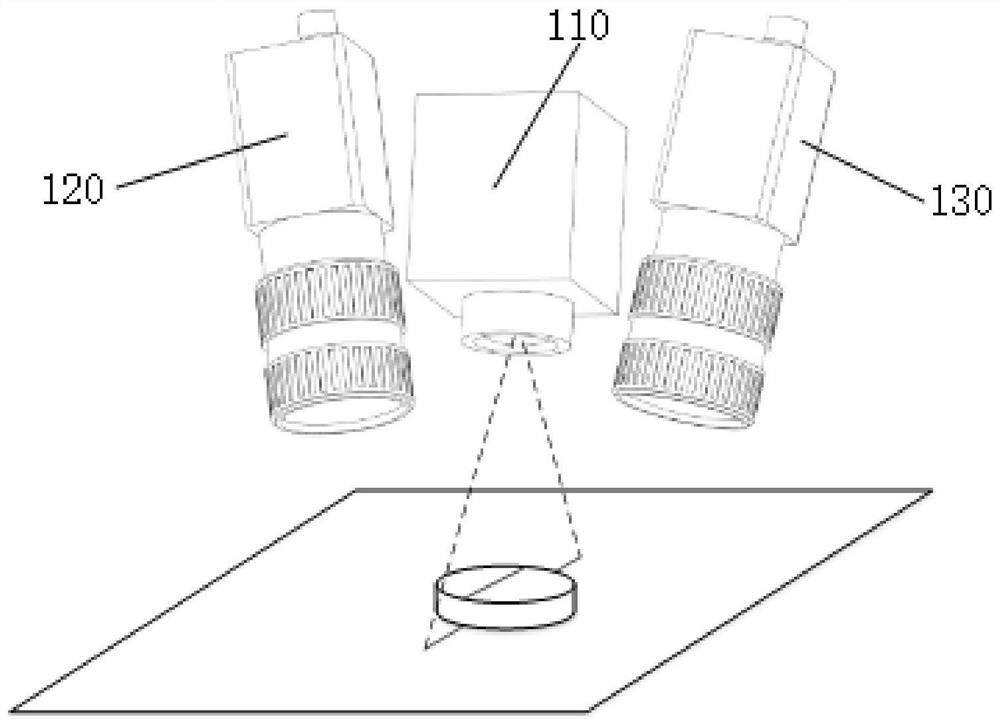
[0046] like Figure 1-3 As shown, the present embodiment provides a method for detecting unevenness of aircraft assembly fasteners, comprising the following steps:

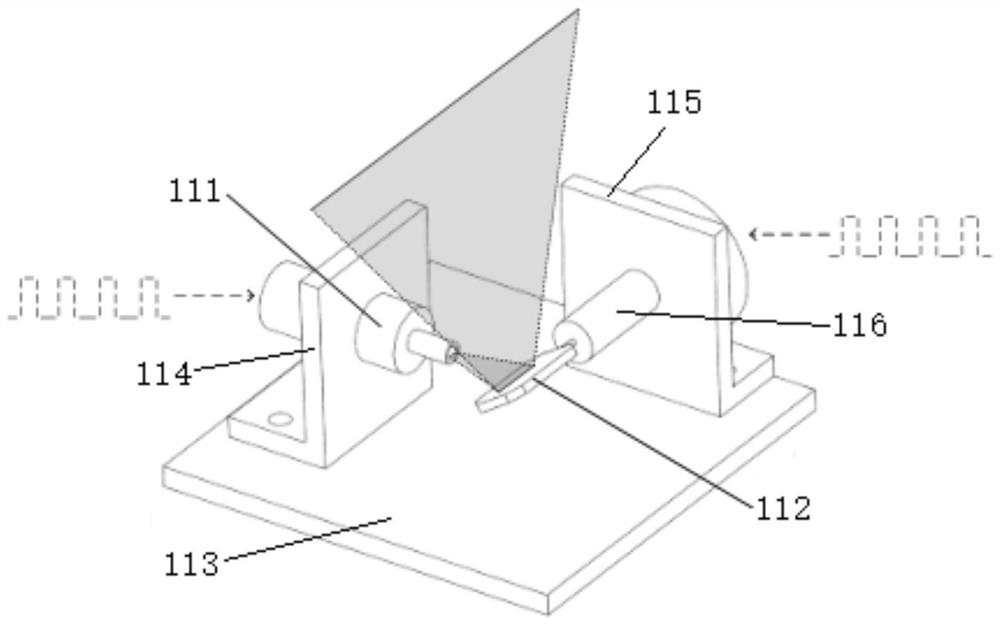
[0047] Step S1: build a detection device, the detection device includes a scanner 110, the first camera 120 and the second camera 130 are respectively arranged on both sides of the scanner 110, the scanner 110 includes a line laser 111 and a one-dimensional vibrating mirror 112, the one-dimensional vibrating mirror 112 is used to reflect the linear laser light projected by the line laser 111 to the surface of the fastener under test;

[0048] Step S2: Output a synchronous square wave signal to the line laser 111 and the one-dimensional vibrating mirror 112 to change the rotation angle of the one-dimensional vibrating mirror 112, the one-dimensional vibrating mirror 112 rotates in a stepwise manner, and the line laser 111 lights up once for each rotation angle , so that the reflected light scans the surface of the...


PUM


Abstract

The invention discloses a method for detecting the concave-convex amount of an aircraft assembly fastener, and relates to the technical field of aeronautical manufacturing surface quality detection, and the method comprises the following steps: S1, a detection device is built; s2, synchronous square wave signals are outputted to a line laser and a one-dimensional galvanometer to change the rotating angle of the one-dimensional galvanometer, wherein the one-dimensional galvanometer rotates in a stepping mode, and the line laser is lightened once every time the one-dimensional galvanometer rotates by one angle; s3, every time the line laser is turned on, the first camera and the second camera store images in a local exposure mode, and the sequence of local exposure is recorded; s4, after one-time scanning is completed, the first camera and the second camera transmit images, the images of the first camera and the second camera are matched according to the exposure time sequence, then three-dimensional calculation is conducted, and point cloud data of the fastener area are obtained; and S5, the point cloud data is analyzed, a high point and a low point in the point cloud data are extracted, and the concave-convex quantity is calculated. The method has the advantages of large data coverage area and accurate extraction of the high point and the low point during detection.

Description

technical field [0001] The invention relates to the technical field of surface quality detection in aviation manufacturing, in particular to a method for detecting the unevenness of aircraft assembly fasteners. Background technique [0002] A large number of fasteners such as rivets and bolts are used in the aircraft assembly process. The height difference between the nail head of the fastener and the surface of the aircraft is called the unevenness. For fighter jets, the unevenness affects the aerodynamic shape and stealth performance of the aircraft. During the construction of the piece, it is necessary to measure the concave and convex amount of the nail head. [0003] The usual measurement method is to use active vision to reconstruct the three-dimensional area of ​​the nail head to form the point cloud data of the area. Common methods include surface structured light method, multi-line laser method, cross laser method, etc. Among them, the surface structured light metho...

Claims


Application Information

Patent Timeline
Patent Type & Authority Applications(China)
IPC IPC(8): G01B11/06
CPCG01B11/06
Inventor 韩利亚喻龙刘子淇周力陈代鑫谢颖李国祥
Owner CHENGDU AIRCRAFT INDUSTRY GROUP
Why Eureka
Try Eureka