Subway platform heat extraction power generation wind ball

A technology for subway platforms and wind bulbs, which is applied in wind power generation, engines, wind power engines, etc., and can solve problems affecting the replacement of wind bulbs for heat dissipation and power generation, low installation efficiency, and easy oxidation and corrosion of fixing nuts.

Inactive Publication Date: 2021-11-09
NANJING VOCATIONAL UNIV OF IND TECH
View PDF0 Cites 0 Cited by
  • Summary
  • Abstract
  • Description
  • Claims
  • Application Information

AI Technical Summary

Problems solved by technology

[0003] The purpose of the present invention is to address the deficiencies of the prior art, and provide a subway platform heat exhaust power generation wind ball to solve the problem that the existing heat exhaust power generation wind ball proposed in the above background technology adopts fixed nuts during the installation process. The surroundings of the heat dissipation and power generation fan bulbs are fixedly connected, which not only results in slow installation speed and low installation efficiency of the overall heat dissipation and power generation fan bulbs, but also the fixing nuts are prone to oxidation and corrosion when they are used for a long time, and at the same time affect the heat dissipation and power generation fan bulbs In the later replacement process, sealants are used to seal the surrounding of the heat dissipation and power generation balloons after the installation of the existing heat dissipation and power generation balloons, which also increases the problems of troublesome installation and low installation efficiency during the installation or replacement of the heat dissipation and power generation balloons

Method used


Image

  • Subway platform heat extraction power generation wind ball
  • Subway platform heat extraction power generation wind ball
  • Subway platform heat extraction power generation wind ball

Examples


Embodiment Construction

[0034] The following will clearly and completely describe the technical solutions in the embodiments of the present invention with reference to the accompanying drawings in the embodiments of the present invention. Obviously, the described embodiments are only some, not all, embodiments of the present invention. Based on the embodiments of the present invention, all other embodiments obtained by persons of ordinary skill in the art without making creative efforts belong to the protection scope of the present invention.

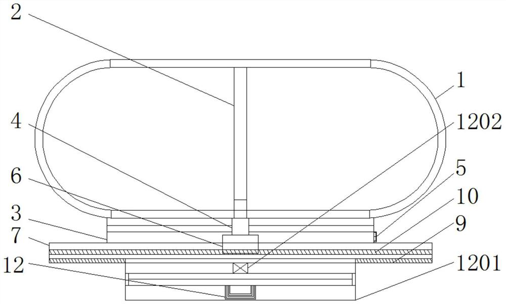
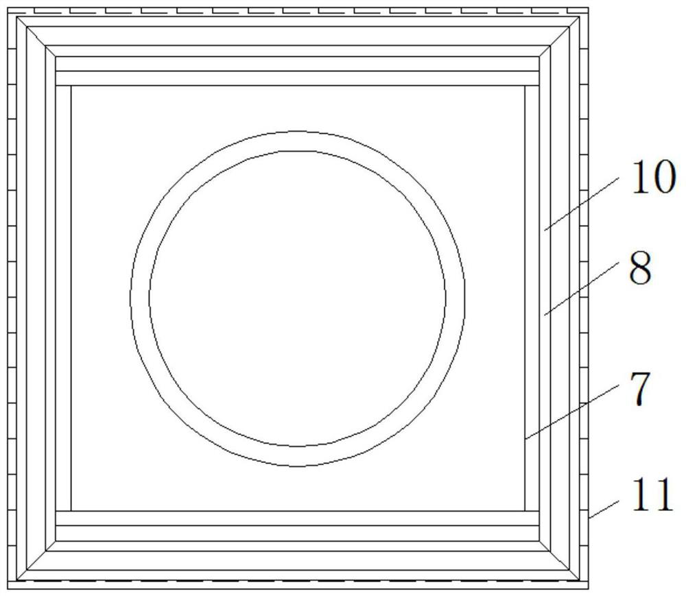
[0035] see Figure 1-6 , the present invention provides a technical solution: a wind bulb for generating heat from a subway platform, such as figure 1 and image 3As shown, the interior of the sphere 1 is fixedly connected to one end of the main shaft 2, the connection bearing 4 is fixed inside the connection seat 3 through a connecting rod, and a multi-directional control button 5 is embedded and fixed on one side of the connection seat 3, and the sphere 1 i...


PUM


Abstract

The invention discloses a subway platform heat extraction power generation wind ball which comprises a ball body, a connecting base, a through hole connecting plate, an edge group and a device convenient to mount and dismount. The interior of the ball body is fixedly connected with one end of a main shaft, a connecting bearing is fixed to the interior of the connecting base through a connecting rod, and the ball body penetrates through the connecting bearing through the other end of the main shaft to be connected with a power generator; clamping grooves are formed in the periphery of the through hole connecting plate, a positive electrode electromagnetic disc is fixed to one side of the through hole connecting plate, magnetic strips are embedded and fixed to the bottom of the edge group, the edge group is clamped and fixed to the periphery of the through hole connecting plate through the clamping grooves, the other end of the connecting base is fixed to the upper portion of the through hole connecting plate, and the positive electrode electromagnetic disc is electrically connected with the power generator and a multi-directional control button through wires. The subway platform heat extraction power generation wind ball is provided with the group edge, the periphery of the through hole connecting plate is wrapped through the group edge, and rainwater falling on the through hole connecting plate flows to a subway platform through the edge group through the edge group to be subjected to flow guide treatment.

Description

technical field [0001] The invention relates to the technical field of subway platforms, in particular to a wind balloon for exhausting heat and generating electricity on a subway platform. Background technique [0002] In the prior art, the main function of the hot air outlet on the top of the platform rail is that when the train is stopped, the train air conditioner condenser is facing the hot air outlet, and the hot air outlet is connected to the hot air duct system on the top of the rail, and there is an OTE fan inside, which is used to discharge the air in the platform. The waste heat and humidity of the tunnel, while the heat, exhaust gas, and humidity in the tunnel are discharged, the instantaneous hot wind energy of the heat exhaust outlet has not been effectively utilized. Wind power generation is to convert the kinetic energy of the wind into mechanical kinetic energy and then into electrical kinetic energy. The wind ball is generally connected to the fixed disk of...

Claims


Application Information

Patent Timeline
Patent Type & Authority Applications(China)
IPC IPC(8): F03G5/06F03D9/11F03D9/43F03D80/00
CPCF03G5/06F03D9/11F03D9/43F03D80/00Y02E70/30Y02E10/72Y02B10/30Y02E10/728
Inventor 何松原周鸿杰徐泽楷
Owner NANJING VOCATIONAL UNIV OF IND TECH
Why Eureka
Try Eureka