Impermeable layer structure for refuse landfill

A technology of landfill and anti-seepage layer, which is applied in the direction of infrastructure engineering, protective devices, buildings, etc., can solve the problems of garbage decomposition, soil and water pollution, pollution, etc., and achieve good anti-seepage effect

Pending Publication Date: 2021-11-09
贵州万通环保工程有限公司
View PDF4 Cites 0 Cited by
  • Summary
  • Abstract
  • Description
  • Claims
  • Application Information

AI Technical Summary

Problems solved by technology

Garbage landfill is a place where garbage is piled up under the sanitary landfill method. Garbage sanitary landfill is widely used in China because of its low cost and good sanitation. Garbage landfill generally adopts the method of layered soil filling to dispose of garbage. For processing, pile up a layer of garbage and then cover it with a layer of loess, which can easily reduce the pollution of garbage; but the main problem that needs to be avoided in the landfill is the anti-seepage problem of the landfill. Garbage will decay and decompose, and once the liquid produced by the decomposition of garbage leaks, it will pollute the soil and water sources, causing serious pollution. The seepage structure should be strictly required, and at the same time, in addition to the possibility of seepage of rotten liquid, the decomposition of garbage will also emit a pungent smell, which affects the environment. Therefore, the invention provides an anti-seepage layer structure for landfills

Method used


Image

  • Impermeable layer structure for refuse landfill

Examples


Embodiment 1

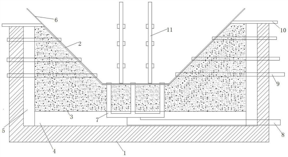
[0019] Such as figure 1 As shown, the structure of the anti-seepage layer for the landfill mainly includes a foundation 1, a landfill pit body 2, a filling layer 3, an isolation layer 4, an adsorption layer 5, an anti-seepage layer 6, a liquid leakage pipe 7, and a liquid outlet pipe 8. Side outlet pipe 9, cover plate 10, liquid inlet pipe 11, the landfill pit body 2 is the pit body on the surface of the foundation 1, the filling layer 3 is arranged outside the landfill pit body 2, and the partition layer 4 is arranged on the filling On the side of layer 3, the landfill pit body 2, partition layer 4, and adsorption layer 5 are integrally formed. After digging the pit body on the surface of the foundation 1, the landfill pit body 2, partition layer 4, and adsorption layer 5 are cut off by concrete slabs. , the landfill pit body 2 is located in the middle, the partition layer 4 is located at the bottom of the landfill pit body 2, and the adsorption layer 5 is located on the left...

Embodiment 2

[0023] An anti-seepage layer structure for a landfill site. The anti-seepage layer structure for a landfill site is to dig a pit on the surface of a foundation as a pit body for landfill, and an anti-seepage layer is laid inside the pit body. The anti-seepage layer It is HDPE film, and the anti-seepage layer is extended to the periphery of the pit body. After the anti-seepage layer is laid, it is filled with garbage. After the garbage is filled, the extended anti-seepage layer is covered on the garbage. After covering, the surface of the anti-seepage layer is covered with soil, planted vegetation, construction When completed, record the completion time;

Embodiment 3

[0025] An anti-seepage layer structure for a landfill site, the anti-seepage layer structure for a landfill site mainly includes a foundation, a landfill pit body, a filling layer, a partition layer, an adsorption layer, an anti-seepage layer, a liquid leakage pipe, an outlet For the liquid pipe, after digging a hole on the surface of the foundation, use a concrete slab to separate the landfill pit body, partition layer, and adsorption layer. The landfill pit body is located in the middle, the partition layer is located at the bottom of the landfill pit body, and the adsorption layer is located On the left and right sides of the landfill pit, liquid leakage pipes and liquid outlet pipes are installed at the bottom of the landfill pit. The foundation is the selected location of the garbage filling site. According to the designed volume, the pit body is dug on the surface of the foundation, and the pit body is dug and installed. The landfill pit body, partition layer, adsorption ...


PUM


Abstract

The invention relates to an impermeable layer structure for a refuse landfill, and belongs to the field of refuse landfill equipment. The impermeable layer structure for the refuse landfill is characterized in that after a pit is dug in the surface of a foundation, a landfill pit body, a separation layer and adsorption layers are separated out through concrete slabs, the landfill pit body is located in the middle position, and the separation layer is located at the bottom of the landfill pit body, the adsorption layers are located on the left side and the right side of the landfill pit body, garbage is landfilled into the landfill pit body, the adsorption layers and a filling layer are filled with adsorption materials, the adsorption materials can adsorb gas generated by garbage decomposition, meanwhile, a liquid leakage pipe and a liquid outlet pipe are arranged at the bottom of the landfill pit body, a side liquid outlet pipe is arranged at the bottom of the landfill pit body, liquid generated by the garbage decomposition can be recycled, and a good impermeable effect can be achieved.

Description

technical field [0001] The invention belongs to the field of garbage landfill treatment equipment, in particular, the invention relates to an anti-seepage layer structure for a garbage landfill. Background technique [0002] Waste disposal methods can generally be divided into several methods such as sanitary landfill, incineration, and composting. Garbage landfill is a place where garbage is piled up under the sanitary landfill method. Garbage sanitary landfill is widely used in China because of its low cost and good sanitation. Garbage landfill generally adopts the method of layered soil filling to dispose of garbage. For processing, pile up a layer of garbage and then cover it with a layer of loess, which can easily reduce the pollution of garbage; but the main problem that needs to be avoided in the landfill is the anti-seepage problem of the landfill. Garbage will decay and decompose, and once the liquid produced by the decomposition of garbage leaks, it will pollute t...

Claims


Application Information

Patent Timeline
IPC IPC(8): E02D31/00E02D31/02
CPCE02D31/006E02D31/02
Inventor 王万海王万田沈洪亿
Owner 贵州万通环保工程有限公司
Why Eureka
Try Eureka