Protective safety shoe production equipment

A technology for production equipment and safety shoes, applied in the field of shoe product processing, can solve the problems of scratched leather, inconvenient accurate detection, inconvenient and rapid appearance of the leather surface, etc., to achieve the effect of improving accuracy

Active Publication Date: 2021-11-09
旭美控股集团有限公司
View PDF5 Cites 0 Cited by
  • Summary
  • Abstract
  • Description
  • Claims
  • Application Information

AI Technical Summary

Problems solved by technology

[0004] But in this technical scheme, when detecting the thickness of leather, by utilizing the first detection sensor in the detection sensing mechanism to directly act on the leather surface for detection, it is easy to scratch the leather due to the first detection sensor, and when the leather is detected, The leather is in a tight state, and the depressions and protrusions on the leather surface are not easy to show quickly, so that accurate detection results cannot be obtained, and it is not easy to complete accurate detection when there are narrow depressions or continuous unevenness on the leather surface

Method used


Image

  • Protective safety shoe production equipment
  • Protective safety shoe production equipment
  • Protective safety shoe production equipment

Examples


Embodiment 1

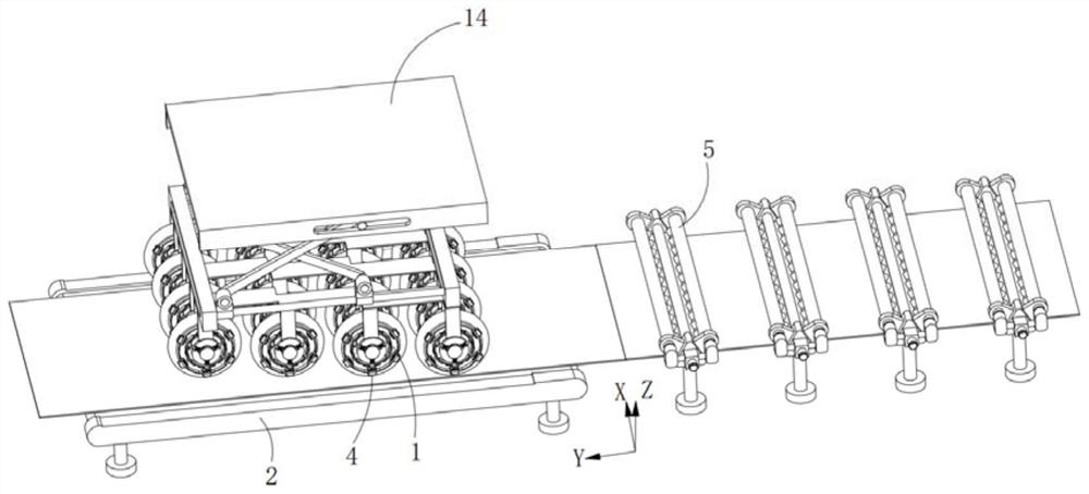
[0043] Such as figure 1 , 2 Shown in and 6, a kind of protective safety shoes production equipment comprises:

[0044] Pressing bladders 1, the pressing bladders 1 are equidistantly arranged along the width direction of leather conveying;

[0045] A pad 2, the pad 2 is provided on the side opposite to the pressure bag 1 on the leather;

[0046] A detection piece 3, the detection piece 3 is arranged in the pressure bag 1 along the leather thickness direction, and the lower end of the detection piece 3 is elastically pressed on the contact surface between the pressure bag 1 and the leather; and

[0047] Marking assembly 4, the marking assembly 4 is arranged on both sides of the pressure bag 1 along the circumferential direction of the pressure bag 1;

[0048] When the detection part 3 detects that the thickness of the leather is less than a predetermined value, the marking print 4 linearly marks both sides of the pressure bag 1 along the leather conveying direction.

[0049]...

Embodiment 2

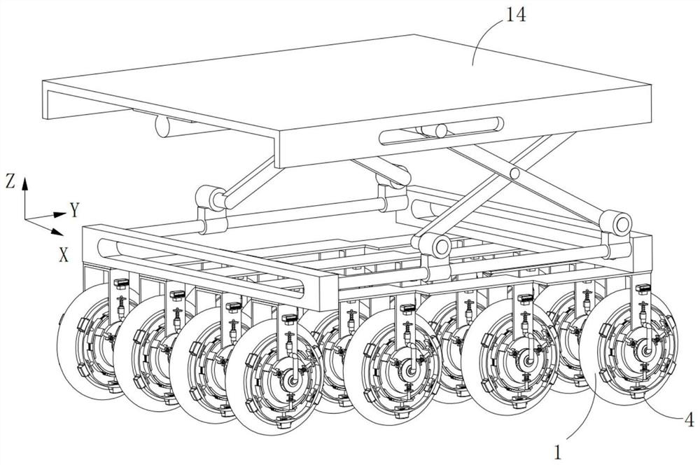
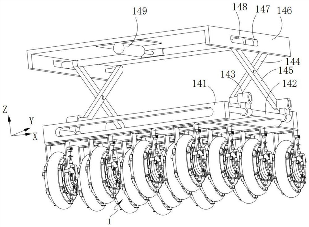
[0075] Such as Figure 6 and 7 As shown, the components that are the same as or corresponding to those in the first embodiment are marked with the corresponding reference numerals in the first embodiment. For the sake of simplicity, only the differences from the first embodiment will be described below. The difference between the second embodiment and the first embodiment is that the pressure bag 1 includes:

[0076] A capsule 11, the capsule 11 is a wheel-shaped structure;

[0077] Insertion shaft 12, the insertion shaft 12 runs through the center of both sides of the capsule 11;

[0078] The second mounting base 13, the second mounting base 13 is fixedly connected to both ends of the insertion shaft 12; and

[0079] Lifting frame 14, described lifting frame 14 is positioned at the top of described second mounting base 12, and described second mounting base 12 is arranged on described lifting frame 13 along leather conveying width direction;

[0080] The lifting frame 14 ...


PUM


Abstract

The invention provides protective safety shoe production equipment, and belongs to the technical field of shoe product processing. The protective safety shoe production equipment comprises pressing bags which are arranged at equal intervals in the width direction of leather conveying, a cushion piece arranged on the side, opposite to the pressing bags, of the leather in a cushion mode, detection pieces arranged in the pressing bags in the thickness direction of the leather and marking assemblies; the lower ends of the detection pieces are elastically pressed on the contact surfaces of the pressing bags and the leather; and the marking assemblies are arranged on the two sides of the pressing bags in the circumferential direction of the pressing bags. When the detecting pieces detect that the thickness of the leather is smaller than a preset value, the marking printing piece linearly marks the two sides of the pressing bags in the leather conveying direction. The equipment has the advantages that the leather thickness detection accuracy is high, and the positions of the leather which does not reach the standard can be rapidly marked.

Description

technical field [0001] The invention relates to the technical field of footwear processing, in particular to production equipment for protective safety shoes. Background technique [0002] In the production process of protective safety shoes, leather materials are used for the production of uppers. When making the shoe upper, the thickness of the leather will be detected in advance, and by detecting the positions on the leather surface whose thickness does not meet the predetermined requirements, avoiding treatment will be performed when the leather is cut to make the shoe upper. [0003] Chinese patent CN211262180U discloses a measuring device for online detection of leather thickness, including a frame and a detection sensor mechanism arranged on the frame, and a detection roller is also rotated on the frame, and the two sides of the detection roller A tension roller is respectively provided, and the tension roller is installed on the frame through the bearing seat; the m...

Claims


Application Information

Patent Timeline
Patent Type & Authority Applications(China)
IPC IPC(8): C14B1/40C14B17/00
CPCC14B1/40
Inventor 项有春
Owner 旭美控股集团有限公司
Why Eureka
Try Eureka