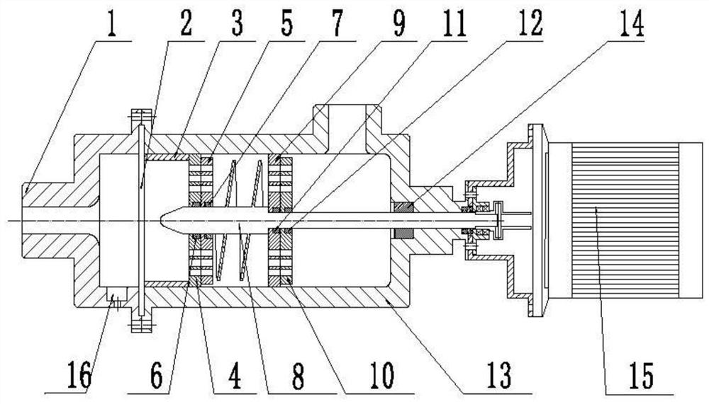
Sewage cavitation degradation treatment device
A technology for treatment device and sewage, applied in the field of sewage cavitation degradation treatment device, can solve the problems of large energy loss and no external power, and achieve the effects of high production efficiency, accelerated collapse and simple operation
- Summary
- Abstract
- Description
- Claims
- Application Information
AI Technical Summary
Problems solved by technology
Method used
Image

Examples
Embodiment 1
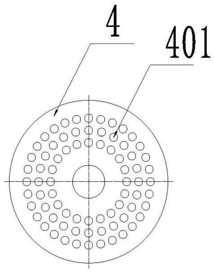
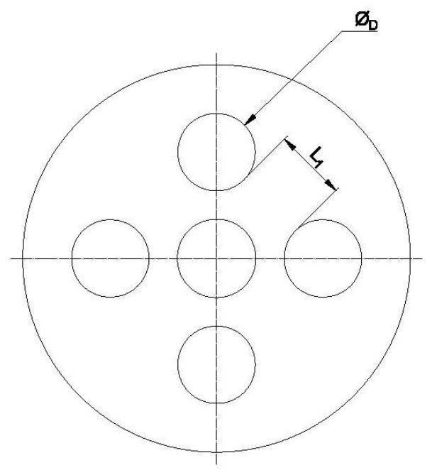
[0039] Example 1 as figure 2 and Figure 2a As shown, the shape of the stator hole 401 is circular, and the circumference of the stator hole 401 is evenly distributed on the first stator 4, and the diameter φ of the stator hole 401 is D Minimum distance L between stator holes 401 adjacent to the same distribution circle 1 The relationship is: 0.25φ D 1 ≤0.75φ D .
Embodiment 2
[0040] Example 2 as image 3 and Figure 3a As shown, the shape of the stator hole 401 is a rectangle, and the length of any side of the stator hole 401 is L 0 Minimum distance L between stator holes 401 adjacent to the same distribution circle 1 The relationship is: 0.25L 0 1 ≤0.5L 0 .
Embodiment 3
[0041] Example 3 as Figure 4 and Figure 4a As shown, the shape of the stator hole 401 is a square, and the length of any side of the stator hole 401 is L 0 Minimum distance L between stator holes 401 adjacent to the same distribution circle 1 The relationship is: 0.25L 0 1 ≤0.5L 0 .
PUM
 Abstract
Description
Claims
Application Information
 - R&D
- Intellectual Property
- Life Sciences
- Materials
- Tech Scout
- Unparalleled Data Quality
- Higher Quality Content
- 60% Fewer Hallucinations
Browse by: Latest US Patents, China's latest patents, Technical Efficacy Thesaurus, Application Domain, Technology Topic, Popular Technical Reports.
© 2025 PatSnap. All rights reserved.Legal|Privacy policy|Modern Slavery Act Transparency Statement|Sitemap|About US| Contact US: help@patsnap.com