Flexible additive manufacturing equipment

An additive manufacturing and equipment technology, applied in the field of flexible additive manufacturing equipment, can solve the problems of slow cooling speed of additive manufacturing raw materials, slow airflow speed, easy to produce softening, etc., to reduce heat transfer, increase solidification speed, Avoid catalytic effects

Inactive Publication Date: 2021-11-09
鲁康权
View PDF0 Cites 0 Cited by
  • Summary
  • Abstract
  • Description
  • Claims
  • Application Information

AI Technical Summary

Problems solved by technology

[0005] Aiming at the deficiencies of the prior art, the present invention provides a flexible additive manufacturing equipment, which solves the problem that the existing flexible additive manufacturing equipment has a relatively slow flow rate of the surrounding airflow during manufacturing, and the cooling speed of the additive manufacturing raw materials is relatively slow. It is easy to soften, lead to self-flow, and produce defects in shaping

Method used


Image

  • Flexible additive manufacturing equipment
  • Flexible additive manufacturing equipment
  • Flexible additive manufacturing equipment

Examples


Embodiment 1

[0034] see Figure 1-3 , the present invention provides a technical solution: a flexible additive manufacturing equipment, specifically comprising:

[0035] Seat plate 1, the seat plate 1 has a circular plate body, and the injection fan 2 installed on the top of the circular plate body, and the manufacturing stage 3 installed on the top of the injection fan 2, and the injection fan 2 installed on the top of the circular plate body The air ring plate 4 on the outside of the fan 2, and the spiral track 5 installed on the inner surface of the air ring plate 4, and the manufacturing device 6 installed on the inner surface of the spiral track 5, and the door 7 installed on the front of the air ring plate 4, through The design of the injection fan 2 and the spiral track 5 circulates and gathers the airflow, and quickly and intensively cools the additively manufactured components to ensure the rapid hardening of the components themselves, preventing excessive accumulation of the comp...

Embodiment 2

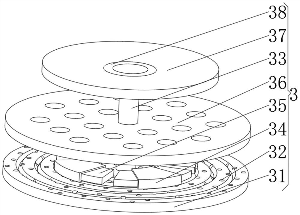
[0041] see Figure 1-5 On the basis of Embodiment 1, the present invention provides a technical solution: the manufacturing device 6 includes:

[0042] Track bar 61, this track bar 61 has convex bar body, and the driver 62 that is installed on the outer surface of convex bar body, and the rotator 63 that is installed on convex bar body two ends, and the shaping machine 64 that is installed in driver 62 bottoms;

[0043] The supply arc plate 65 has an inner through plate body, a bearing cylinder 66 installed on the top of the inner through plate body, and a mixing device 67 installed on the bottom of the inner cavity of the bearing cylinder 66 . The design of the supply arc plate 65 separates the upper and lower components, reduces heat transfer, protects the components from thermal fatigue, and at the same time reduces the temperature of the raw materials for additive manufacturing, increasing the solidification speed of the raw materials.

[0044] The outer surface of the sp...


PUM


Abstract

The invention discloses flexible additive manufacturing equipment. The flexible additive manufacturing equipment specifically comprises a base plate, an air injection fan, a manufacturing carrying table, a spiral rail and a manufacturing device, wherein the air injection fan is mounted at the top of a circular plate body, the manufacturing carrying table is mounted at the top of the air injection fan, the spiral rail is mounted on the inner surface of an air ring plate, and the manufacturing device is mounted on the inner surface of the spiral rail; and the manufacturing carrying table comprises a threaded disc, an auxiliary rotating shaft,a wind shielding plate, telescopic elastic plates and a breathable carrying disc, wherein the auxiliary rotating shaft is mounted in the middle of the top of the disc body, the wind shielding plate is mounted at the top of the disc body, the telescopic elastic plates are mounted on the two sides of the wind shielding plate, and the breathable carrying disc is mounted at the top of the auxiliary rotating shaft. The invention relates to the technical field of robot transportation equipment. Through the design of the air injection fan and the spiral rail, air flow is circularly gathered, and members for additive manufacturing are rapidly cooled in a concentrated mode, so that it is ensured that the members are rapidly hardened, the members are prevented from being excessively accumulated due to softening in the temperature process of the members, and the members are prevented from being damaged.

Description

technical field [0001] The invention relates to the technical field of additive manufacturing, in particular to a flexible additive manufacturing equipment. Background technique [0002] The principle of additive manufacturing is to use computer-aided software to create a three-dimensional solid model of the part, and obtain the two-dimensional data of each thin surface of the part through layering software, so as to obtain the sweeping path of the energy beam, and process it by sweeping liquid, powder or thin sheet materials Thin layers of the required shape are produced and accumulated layer by layer to form a solid model. [0003] Existing flexible additive manufacturing equipment has a slow flow rate of air around itself during manufacturing, and the cooling speed of additive manufacturing raw materials is slow, and it is easy to soften itself, resulting in its own flow and forming defects. Contents of the invention [0004] Technical issues resolved [0005] Aiming ...

Claims


Application Information

Patent Timeline
IPC IPC(8): B29C64/20B29C64/314B33Y30/00B33Y40/10
CPCB29C64/20B29C64/314B33Y30/00B33Y40/10
Inventor 鲁康权
Owner 鲁康权
Why Eureka
Try Eureka