
Electric jet printing device capable of dredging spray head through variable-pressure airflow

A technology of electrojet printing and nozzles, applied in coating devices, manufacturing auxiliary devices, additive manufacturing, etc., can solve the problems of functional ink texture stability, long processing cycle, and difficulty in dredging, and achieve the optimization of micro-nano functional structure , short processing cycle and low equipment cost

Pending Publication Date: 2021-11-09
NINGBO UNIV
View PDF4 Cites 6 Cited by
  • Summary
  • Abstract
  • Description
  • Claims
  • Application Information

AI Technical Summary

Problems solved by technology

However, using the above two dredging methods will have many adverse effects on printing
[0004] 1. To dredge the nozzle by mechanical vibration and physical heating, the nozzle needs to be disassembled from the printing equipment. The processing cycle is long, the process is cumbersome, and it is not easy to operate. Especially when the inner diameter of the nozzle is small, it is more difficult to dredge.
[0005] 2. The mechanical vibration method is simple, but if the nozzle is placed in a vibrating environment, the solid particle impurities will be crushed, and the texture stability of the functional ink will also be affected.

Method used


Image

  • Electric jet printing device capable of dredging spray head through variable-pressure airflow
  • Electric jet printing device capable of dredging spray head through variable-pressure airflow
  • Electric jet printing device capable of dredging spray head through variable-pressure airflow

Examples


Embodiment Construction

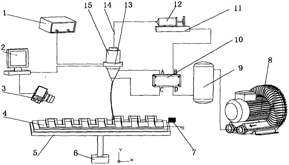
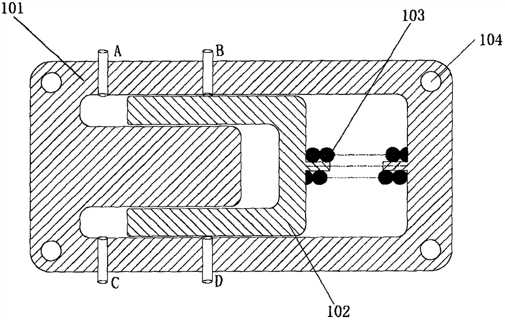
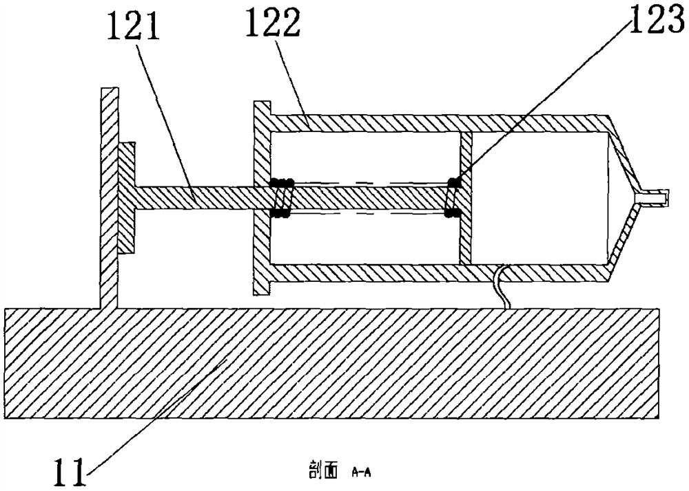
[0026] The specific implementation manner of the present invention will be described in detail below in conjunction with the technical scheme and the accompanying drawings. see Figure 1 to Figure 3 .

[0027] This embodiment discloses an electrojet printing device for dredging nozzles with variable pressure airflow, which includes four parts: a jet printing module, a visual detection module, an adsorption module and an air pressure dredging nozzle module. Based on the electrohydrodynamic effect, the functional ink 14 is delivered to the nozzle at a fixed flow rate, and then under the combined action of electric field force, gravity, and surface tension, a nano-scale fine jet is formed to quickly realize the preparation of micro-nano functional structures; when the nozzle is blocked , two-position four-way valve 10 actions, using variable pressure airflow to apply reciprocating pressure and suction to the blockage of the nozzle, realizing disassembly-free, automatic dredging ...


PUM


Abstract

The invention belongs to the technical field of advanced manufacturing, and relates to an electric jet printing device capable of dredging spray head through a variable-pressure airflow. The electric jet printing device comprises four parts, namely a jet printing module, a visual detection module, an adsorption module and an air pressure dredging spray head module, the jet flow jetted based on the electrohydrodynamic effect quickly realizes micro-nano functional structure jet printing under the coupling action of factors such as electric field force and viscous force. The electronic jet printing device adopts a mode of dredging the spray head through the variable-pressure airflow, when the spray head is blocked, accumulated ink in a spray head cavity is increased, unit pressure is increased, a core device, namely a two-position four-way valve acts, and the variable-pressure airflow applies reciprocating pressure and suction force to the blocked part, so that the spray head is dredged. Compared with a traditional method for dredging the spray head through mechanical vibration and physical heating, the electronic jet printing device has the advantages that the equipment cost is low, the machining period is short, disassembly is avoided, the spray head is automatically dredged, it is guaranteed that discontinuous, continuous and stable nanoscale fine jet flow is not generated in the jet printing process, a micro-nano functional structure is optimized, the use performance of a nano device is improved, and the service life of the nano device is prolonged.

Description

technical field [0001] The invention belongs to the field of advanced manufacturing technology, and relates to an electrojet printing device for dredging nozzles with a variable pressure airflow. Background technique [0002] Electrojet printing technology is a high-precision non-contact additive manufacturing technology. It uses fluid pressure to supply functional ink to the outlet of the nozzle to form initial hanging droplets. A high voltage is applied between the nozzle and the substrate, and the electric field force is used to The coupling effect of factors such as viscous force and other factors makes the ink form a stable focused jet with a diameter much smaller than the inner diameter of the nozzle hole at the nozzle hole, through which the required micro-nano functional structure can be prepared on the substrate. Due to the advantages of high processing precision, high material utilization rate, simple process, and strong printing controllability, electrojet printin...

Claims


Application Information

Patent Timeline
IPC IPC(8): B29C64/20B29C64/135B29C64/209B29C64/205B29C64/245B29C64/321B29C64/35B29C64/314B29C64/393B33Y30/00B33Y40/10B33Y40/00B33Y50/02
CPCB29C64/20B29C64/135B29C64/209B29C64/205B29C64/245B29C64/321B29C64/35B29C64/314B29C64/393B33Y30/00B33Y40/10B33Y40/00B33Y50/02
Inventor 李凯任鑫磊尤诚诚刘麦祺王晓英
Owner NINGBO UNIV
Learn More