


Quick Research
Generate reliable direction feasibility study reports for your R&D in just a few steps.

Technical Q&A
Discover and master advanced knowledge NOW. Basics, ideas, possibilities, all at once.

Find Solutions
As an expert in R&D theories, this can generate solutions to your technical problems instantly.

Evaluate Feasibility
Analyze your overall solution with one click, know your potential R&D risks in advance.

Monitor Landscape
Get weekly tech updates, stay abreast of the latest tech innovations and key insights.
Bottom buckling and winding device for tinplate can machining
A technology for tinplate cans and winding devices, which is applied in metal processing equipment, applications, household appliances, etc., can solve the problem that the bottom of the can and the mold are not easy to take out, affect the production efficiency, and the winding device cannot be used. The problem of poor shape effect, etc., can achieve the effect of good shape, no need for maintenance, and prevention of excessive temperature.
- Summary
- Abstract
- Description
- Claims
- Application Information
AI Technical Summary
Problems solved by technology
Method used
Image

Examples
Embodiment 1
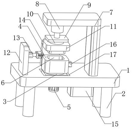
[0037] see Figure 1-9, the present invention provides a technical solution: a buckle bottom winding device for tinplate can processing, including a workbench 1, the bottom of the workbench 1 is fixedly connected with evenly distributed legs 2, and the top of the leg 2 is rotatably connected with The first rotating shaft 3, the top of the first rotating shaft 3 is fixedly connected with the lower mold 4, the bottom of the workbench 1 is fixedly connected with the first motor 5, and the output end of the first motor 5 is fixedly connected with the bottom of the first rotating shaft 3 , the top of the lower mold 4 is provided with a forming groove 6, the top of the workbench 1 is fixedly connected with a support plate 7, the bottom of the support plate 7 is fixedly connected with a stamping cylinder 8, the top of the workbench 1 is provided with a fixed plate 9, and the fixed plate 9 The top of the top is fixedly connected with the piston rod of the stamping cylinder 8, the bott...
Embodiment 2
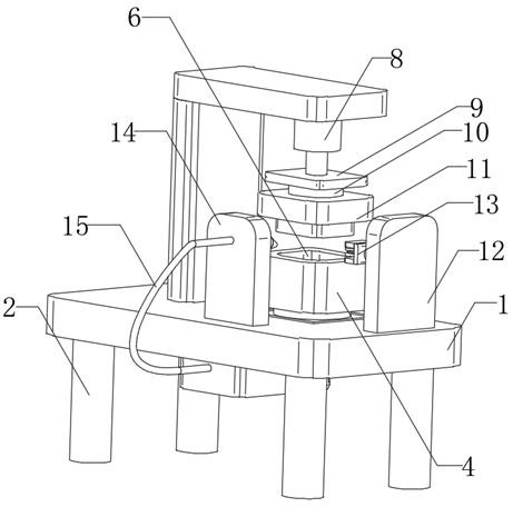
[0040] Such as Figure 1-9 As shown, on the basis of Embodiment 1, the present invention provides a technical solution: one side of the lower mold 4 is provided with a cooling assembly 15, and the cooling assembly 15 includes a water tank 1501, a water pump 1502, a first connecting pipe 1503 and a nozzle 1504, The water tank 1501 is fixedly connected to the bottom of the workbench 1, the water pump 1502 is fixedly connected to the inside of the water tank 1501, the top of the workbench 1 is fixedly connected to the second clamping plate 14, and the nozzle 1504 is fixedly connected to the second clamping plate 14 close to the lower mold 4, the first connecting pipe 1503 is fixedly connected to the output end of the water pump 1502, and the first connecting pipe 1503 communicates with the spray head 1504.
[0041] In this embodiment, the water pump 1502 will pump the pre-stored water inside the water tank 1501 through the first connecting pipe 1503 to the inside of the nozzle 15...
Embodiment 3
[0043] Such as Figure 1-9 As shown, on the basis of Embodiment 1 and Embodiment 2, the present invention provides a technical solution: the inside of the lower mold 4 is fixedly connected with a sliding sleeve 24, and the inside of the sliding sleeve 24 is movably inserted with a jacking rod 19. The outside of the lifting rod 19 is fixedly sleeved with the limit plate 20, and the inside of the lower mold 4 is fixedly connected to the second motor 22, and the output end of the second motor 22 is fixedly connected to the triangular rotor 23, and the triangular rotor 23 is located under the lifting rod 19. A spring 21 is sleeved on the outside of the jacking rod 19 , and the spring 21 is located between the sliding sleeve 24 and the limiting plate 20 .
[0044] In this embodiment, the second motor 22 is started, so that the output end of the second motor 22 drives the triangular rotor 23 to rotate, thereby driving the jacking rod 19 to lift upwards, so as to push the bottom iron...
PUM
 Abstract
Description
Claims
Application Information
 - R&D Engineer
- R&D Manager
- IP Professional
- Industry Leading Data Capabilities
- Powerful AI technology
- Patent DNA Extraction
Browse by: Latest US Patents, China's latest patents, Technical Efficacy Thesaurus, Application Domain, Technology Topic, Popular Technical Reports.
© 2024 PatSnap. All rights reserved.Legal|Privacy policy|Modern Slavery Act Transparency Statement|Sitemap|About US| Contact US: help@patsnap.com