
Filtering device for greenhouse gas emission

A filtration device and technology for greenhouse gases, which are applied in the fields of dispersed particle filtration, dispersed particle separation, chemical instruments and methods, etc., can solve the problems of inability to filter greenhouse gases, inconvenient disassembly and replacement, etc., and achieve good heat insulation effect and improve filtration effect. , good filtering effect

Pending Publication Date: 2021-11-09
江苏嘉斌环保科技有限公司
View PDF6 Cites 0 Cited by
  • Summary
  • Abstract
  • Description
  • Claims
  • Application Information

AI Technical Summary

Problems solved by technology

[0003] When the existing filter device is in use, there is only one filter structure inside, which can only be filtered once, and cannot completely filter the greenhouse gas. Moreover, the filter structure in the existing filter device is fixed inside the device, which is inconvenient to disassemble and replace.

Method used


Image

  • Filtering device for greenhouse gas emission
  • Filtering device for greenhouse gas emission
  • Filtering device for greenhouse gas emission

Examples


Embodiment 1

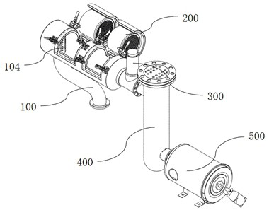
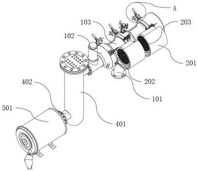
[0030] refer to Figure 1~Figure 6 , a filter device for greenhouse gas emissions is proposed in this embodiment, comprising:

[0031] Pipe mechanism 100: including combustion pipe 102, which is a circular steel tank body, and an air intake pipe 101 is installed on one side of combustion pipe 102;

[0032] Purification mechanism 200: it is installed on the outside of the combustion tube 102, including a connecting buckle 202 that drives the rotation of the flip door 201 and a quick replacement component, and a filter element 203 is installed on one side of the two flip doors 201;

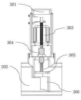
[0033] Valve mechanism 300: including a connecting pipe 302 connected to the combustion pipe 102 and an electric control assembly;

[0034] Heat dissipation mechanism 400: includes a heat dissipation pipe 401 and an interface 402, which is connected to the connecting pipe 302 through the interface 402, the two interfaces 402 are installed on both sides of the heat dissipation pipe 401, and a heat d...

Embodiment 2

[0047] The exhaust pipe is connected to the intake pipe 101. When the exhaust gas is not discharged, the cylinder 303 drives the air-tight plug 305 to close, and the connecting pipe 302 is blocked. The exhaust gas continues to accumulate in the combustion pipe 102, increasing the internal pressure and temperature of the combustion pipe 102. The exhaust gas contacts the filter element 203, Since the catalyst in the filter element 203 needs to reach a higher reaction rate under a certain temperature and pressure, the temperature sensor and the pressure sensor monitor the internal conditions of the combustion tube 102 in real time, and the temperature and pressure are controlled within a certain range. When the temperature is high, the cylinder 303 starts to open the air-blocking plug 305, and the exhaust gas is discharged to prevent the device from being damaged due to excessive internal pressure and reduce the filtering effect when the pressure is low. When the temperature and pr...


PUM


Abstract

The invention discloses a filtering device for greenhouse gas emission, comprising: a pipeline mechanism comprising a combustion pipe which is a circular steel tank body, and one side of the combustion pipe is provided with a gas inlet pipe; a purification mechanism which is mounted on the outer side of the combustion pipe; a valve mechanism which comprises a connecting pipe connected with the combustion pipe and an electric control assembly; a heat dissipation mechanism which is connected with the connecting pipe through an interface; and an exhaust mechanism which is connected with an interface bolt on one side of the heat dissipation pipe through an exhaust shell. According to the filtering device provided by the invention, gas is filtered through the filter elements which are arranged in sequence, so that the filtering effect is improved, and the emission of greenhouse gas is reduced; by arranging a rapid replacement assembly, a filter element can be rapidly taken out and replaced, the working efficiency is improved, an sensor can electrically control an air cylinder, the situation that the device is damaged due to the fact that the internal pressure is too large and the filtering effect is reduced when the pressure is small is prevented, the controllability of the filtering efficiency is achieved, and the safety is greatly improved.

Description

technical field [0001] The invention relates to the field of filtering greenhouse gas emissions, in particular to a filtering device for greenhouse gas emissions. Background technique [0002] Global warming is the most important environmental problem faced by mankind so far, and one of the most complex challenges faced by mankind in the 21st century. At the same time, it is the key to the world's energy prospects and has become an important factor affecting the world's economy and politics. The emission of carbon-based greenhouse gases caused by human activities is the main cause of global warming. At present, issues related to anthropogenic carbon emissions have become the main research objects of various countries. As the world's energy and environmental problems become more and more serious, while my country is developing its economy rapidly, it must be committed to ensuring the coordinated development of economic development, energy consumption and environmental protec...

Claims


Application Information

Patent Timeline
Patent Type & Authority Applications(China)
IPC IPC(8): B01D53/86B01D46/24B01D53/50B01D53/56B01D53/70
CPCB01D53/8628B01D53/8609B01D46/2403B01D53/8662B01D2255/20707B01D2255/20723B01D2255/20769B01D2255/20776
Inventor 潘嘉斌
Owner 江苏嘉斌环保科技有限公司
Learn More