Two-way clutch

A technology of two-way clutches and engaging parts, which is applied to one-way clutches, clutches, mechanical equipment, etc., can solve the problems of axial enlargement of two-way clutches, and achieve the effect of compact axial size.

Active Publication Date: 2021-11-05
SUGATSUNE IND CO LTD
View PDF7 Cites 0 Cited by
  • Summary
  • Abstract
  • Description
  • Claims
  • Application Information

AI Technical Summary

Problems solved by technology

Therefore, there is a problem that the axial direction of the two-way clutch tends to be larger

Method used


Image

  • Two-way clutch
  • Two-way clutch
  • Two-way clutch

Examples


Embodiment Construction

[0026] The two-way clutch according to the embodiment of the present invention will be described in detail below with reference to the accompanying drawings. However, the two-way clutch of the present invention can be realized in various forms, and is not limited to the embodiments described in this specification. The present embodiment is provided only for the purpose of enabling those skilled in the art to fully understand the scope of the invention by sufficiently disclosing the specification.

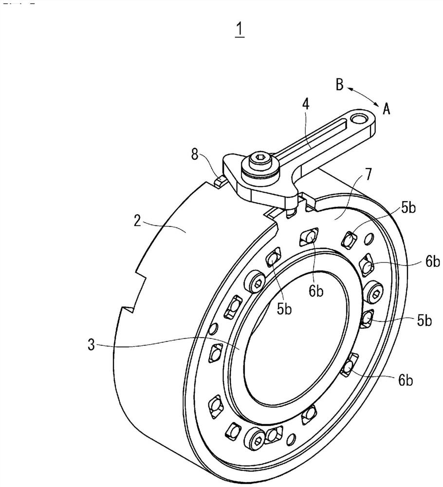
[0027] figure 1 An external perspective view of a two-way clutch according to an embodiment of the present invention is given. The two-way clutch 1 of the present embodiment includes an outer ring 2 as an outer member, an inner ring 3 as an inner member, and a group of first rollers 5 ( figure 1 Shaft 5b) of the first roller 5 group, the second roller 6 group ( figure 1 The shaft 6b) of the second roller group 6, the first cage 7, the second cage 8, and the shank 4 are shown.

...


PUM


Abstract

Provided is a two-way clutch of which the size in the axial direction can be made compact. A first engaging piece (5) and a second engaging piece (6) are disposed in a first wedge-shaped space (S1) and a second wedge-shaped space (S2) between an outer member (2) and an inner member (3). The first engaging piece (5) is held by a first holder (7), and the first holder (7) is enabled to oscillate within the outer member (2). The second engaging piece (6) is held in a second holder (8), and the second holder (8) is enabled to oscillate within the outer member (2). In a side surface view orthogonal to the axial direction of the first engaging piece (5) and the second engaging piece (6), at least part of the first engaging piece (5) and at least part of the second engaging piece (6) overlap in the axial direction. The first holder (7) is configured so as to allow the second engaging piece (6) to oscillate along with the second holder (8). The second holder (8) is configured so as to allow the first engaging piece (5) to oscillate along with the first holder (7).

Description

technical field [0001] The present invention relates to a two-way clutch for locking and unlocking two-way (clockwise and counterclockwise) rotation. Background technique [0002] As such a two-way clutch, that described in JP-A-2008-057566 is known. This conventional two-way clutch includes an outer member, an inner member arranged inside the outer member, and first and second engaging members arranged between the outer member and the inner member. A plurality of cam surfaces forming a plurality of wedge-shaped cavities between the inner member and the inner member are formed on the inner face of the outer member. The first engaging parts and the second engaging parts are arranged in the plurality of wedge-shaped cavities. The first engaging piece is held by the first holder. The first retainer swings relative to the outer member, so that the first engaging member engages and disengages with the cam surface. The second engaging piece is held by the second holder. The s...

Claims


Application Information

Patent Timeline
Patent Type & Authority Applications(China)
IPC IPC(8): F16D41/08
CPCF16D41/067F16D41/088
Inventor 安斋忠志
Owner SUGATSUNE IND CO LTD
Why Eureka
Try Eureka