Flywheel energy storage system and control method thereof

A flywheel energy storage and control method technology, which is applied in the field of flywheel energy storage system and its control, can solve the problems of low system efficiency, large loss, high cost, etc., and achieve the effects of improving overall efficiency, reducing loss, and low cost

Active Publication Date: 2022-02-11
TIANJIN EMAGING TECH
View PDF5 Cites 0 Cited by
  • Summary
  • Abstract
  • Description
  • Claims
  • Application Information

AI Technical Summary

Problems solved by technology

[0003] The purpose of the present invention is to provide a flywheel energy storage system and its control method, so as to alleviate the technical problems of high device requirements, prominent insulation problems, high cost, large loss and low system efficiency existing in the prior art

Method used


Image

  • Flywheel energy storage system and control method thereof
  • Flywheel energy storage system and control method thereof
  • Flywheel energy storage system and control method thereof

Examples


Embodiment 1

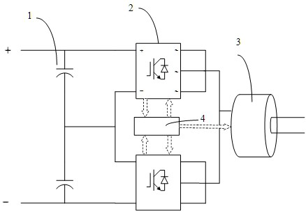
[0037] figure 2 A schematic structural diagram of a flywheel energy storage system provided in an embodiment of the present invention, such as figure 2 As shown, the system includes: a capacitor bank, at least two three-phase inverter bridges 2 , at least one motor 3 and a control unit 4 . The connection relationship between the above modules is as follows: the capacitor bank is connected to the high-voltage power supply, all capacitors 1 in the capacitor bank are connected in series in sequence, the number of capacitors 1 is consistent with the number of three-phase inverter bridges 2, and the positive pole of each capacitor 1 is It is connected with the positive pole of the DC side of the corresponding three-phase inverter bridge 2, the negative pole of each capacitor 1 is connected with the negative pole of the DC side of the corresponding three-phase inverter bridge 2, and the AC side of the three-phase inverter bridge 2 is connected with the motor 3 One end is connecte...

Embodiment 2

[0070] According to an embodiment of the present invention, an embodiment of a control method for a flywheel energy storage system is provided. It should be noted that the steps shown in the flow charts of the drawings can be executed in a computer system such as a set of computer-executable instructions , and, although a logical order is shown in the flowcharts, in some cases the steps shown or described may be performed in an order different from that shown or described herein.

[0071] Figure 9 A flow chart of a control method for a flywheel energy storage system provided by an embodiment of the present invention is applied to the control unit in the flywheel energy storage system as described in Embodiment 1, such as Figure 9 As shown, the method includes the following steps:

[0072] Step S101, obtaining the actual voltages of all capacitors and the AC side currents of all three-phase inverter bridges;

[0073] Step S102 , in the charging stage of the flywheel energy ...


PUM


Abstract

The present invention provides a flywheel energy storage system and its control method, relating to the technical field of flywheel energy storage, including: a capacitor bank, at least two three-phase inverter bridges, at least one motor and a control unit; the control unit uses The control unit is used to obtain the actual voltage of all capacitors and the AC side current of all three-phase inverter bridges; the control unit is also used to control the voltage equalization of capacitors according to the actual voltage and the torque current of the motor during the charging phase of the flywheel energy storage system The method controls the torque currents of all motors to realize voltage equalization control on all capacitors. The present invention can divide the voltage provided by the high-voltage power supply equally and reduce the input of the DC side of the three-phase inverter bridge by connecting at least two DC sides of the three-phase inverter bridge in series and combining the corresponding capacitor voltage equalization control method. Therefore, the three-phase inverter bridge can use low-voltage switching devices to reduce the loss of the three-phase inverter bridge and the motor, and improve the overall efficiency of the flywheel energy storage system.

Description

technical field [0001] The invention relates to the technical field of flywheel energy storage, in particular to a flywheel energy storage system and a control method thereof. Background technique [0002] The existing flywheel energy storage system includes a power converter, a motor driver, a motor and a flywheel connected in sequence. In some application scenarios of flywheel energy storage, the input voltage of the DC side is very high. For example, in the case of subway braking, the subway traction power supply usually provides 1500V DC. At this time, the terminal voltage of the motor in the existing flywheel energy storage system needs Only by being transformed into 1500V DC can the energy exchange with the power supply be realized. In this case, the existing technology usually adopts the following three methods to realize energy exchange: the first method is that the motor terminal voltage adopts a conventional low-voltage 380V, and the motor driver is used to direct...

Claims


Application Information

Patent Timeline
Patent Type & Authority Patents(China)
IPC IPC(8): H02J15/00H02P27/06
CPCH02J15/007H02P27/06Y02E60/16
Inventor 魏庆毕刘新沙宏磊俞天野潘洪涛
Owner TIANJIN EMAGING TECH
Why Eureka
Try Eureka