
Connector

A connector and conductive connection technology, applied in the direction of connection, two-part connection device, and parts of the connection device, etc., can solve the problems of easy piercing of the internal parts of the box, and reduce the pressure, width, size, etc. The effect of a large contact area

Pending Publication Date: 2021-11-05
郑州深澜动力科技有限公司
View PDF1 Cites 0 Cited by
  • Summary
  • Abstract
  • Description
  • Claims
  • Application Information

AI Technical Summary

Problems solved by technology

[0006] The purpose of the present invention is to provide a connector to solve the technical problem in the prior art that the vertical side arm of the L-shaped conductive row is easy to pierce the internal parts of the box when the connector is squeezed

Method used


Image

  • Connector
  • Connector
  • Connector

Examples


Embodiment 1

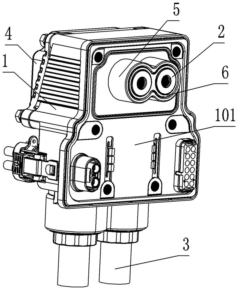
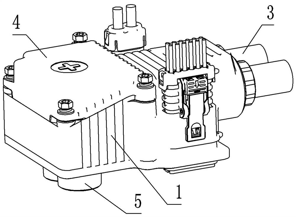
[0050] Such as figure 1 and figure 2 As shown, the connector includes a housing 1, and a conductive member is provided in the housing 1. The conductive member in this embodiment is a conductive post 2, and the conductive post 2 is used for conductive connection with the wire 3 in the housing 1.

[0051] The connector in this embodiment is connected with two wires 3 , and the arrangement of the two wires 3 can prevent the single wire from being too large in diameter and inconvenient to be bent, thereby inconvenient for installation and wiring. There are two conductive columns 2 that cooperate with the two wires 3 to form a conductive connection, and the two conductive columns 2 are arranged side by side and spaced apart.

[0052] The housing 1 has an installation side 101, which is used to be fixed and press-fitted on the box wall of the corresponding box, so that the connector is fixedly connected with the corresponding box.

[0053] In order to describe this embodiment mor...

Embodiment 2

[0075] The difference between this embodiment and Embodiment 1 is that the connector in Embodiment 1 is connected with two wires, and two corresponding conductive columns are provided to realize conductive connection with the two wires respectively, while in this embodiment , the connector is only provided with one wire, and the corresponding conductive post is provided with one, so as to realize the conductive connection.

Embodiment 3

[0077] The difference between this embodiment and Embodiment 1 is that the conductive column in Embodiment 1 includes an inner cylinder and an outer cylinder, and the inner cylinder and the outer cylinder are respectively used for connecting wires and external conductive bars, while in this embodiment Among them, the conductive column is an integral cylinder, and the two ends of the conductive column are respectively used to connect the wire and the external conductive bar. Correspondingly, the external conductive bar has a wider section, and the wider section of the external conductive bar is provided with Holes for bolts for fitting connection with conductive posts.


PUM


Abstract

The invention relates to a connector. The connector comprises a connector shell, a conductive piece is arranged in the connector shell, and the conductive piece is used for being conductively connected with a wire; the conductive piece is provided with an exposed end face, and the exposed end face is parallel to or inclined to the mounting side face; a conductive bar installation structure is arranged on the exposed end face and used for pressing the wide face of a corresponding external conductive bar on the exposed end face, and the wide face of the external conductive bar is perpendicular to the thickness direction of the external conductive bar. When the connector is subjected to external pressure, the wide surface of the external conductive bar is used as a force bearing surface, so that a relatively large contact area can be achieved, and the pressure intensity at a top pressing part is reduced, and therefore, a corresponding insulation protection part is not easy to puncture to be in contact with a metal part, and the problems of insulation fault, short circuit and potential safety hazard which are liable to occur when the connector is extruded are avoided.

Description

technical field [0001] The invention relates to a connector. Background technique [0002] In the power battery system, the electrical connection technology is widely used. The external electrical connection part of the battery box should not only meet the reliability of conducting a large current for a long time, but also consider its anti-extrusion ability to prevent local deformation after extrusion, resulting in Internal short circuit of electrical connectors, localized ablation or fire. [0003] For example, an integrated connector disclosed in a Chinese patent whose authorized notification number is CN208923473U has a two-pin plug and a multi-pin plug on the integrated base to meet various functional requirements of the connector. The connector is also provided with a conductive bar for fixed connection with an externally adapted conductive bar. [0004] The installation side on this connector is parallel to the corresponding installation side wall of the box body, a...

Claims


Application Information

Patent Timeline
IPC IPC(8): H01R13/02H01R24/00H01R13/40H01R13/502H01R13/52H01M50/503
CPCH01R13/02H01R24/00H01R13/40H01R13/502H01R13/521
Inventor 张广超张红涛孙书伟
Owner 郑州深澜动力科技有限公司
Learn More