Image artifact elimination method and device and equipment
An image and input image technology, applied in the field of image artifact removal, can solve the problems of beam hardening artifacts, affecting the analysis accuracy of the microscopic structure of the scanned object, etc., to achieve improved quality, effective and accurate data base, strong practicability Effect
- Summary
- Abstract
- Description
- Claims
- Application Information
AI Technical Summary
Problems solved by technology
Method used
Image


Examples
Embodiment 1
[0062] refer to figure 1 A schematic flow chart of the present invention proposes a first embodiment of an image artifact elimination method, which is applied to an image artifact elimination device.
[0063] The image artifact elimination device refers to a terminal device or network device that can realize network connection, and the image artifact elimination device can be a terminal device such as a mobile phone, a computer, a tablet computer, an embedded industrial computer, or a server, a cloud platform and other network equipment.
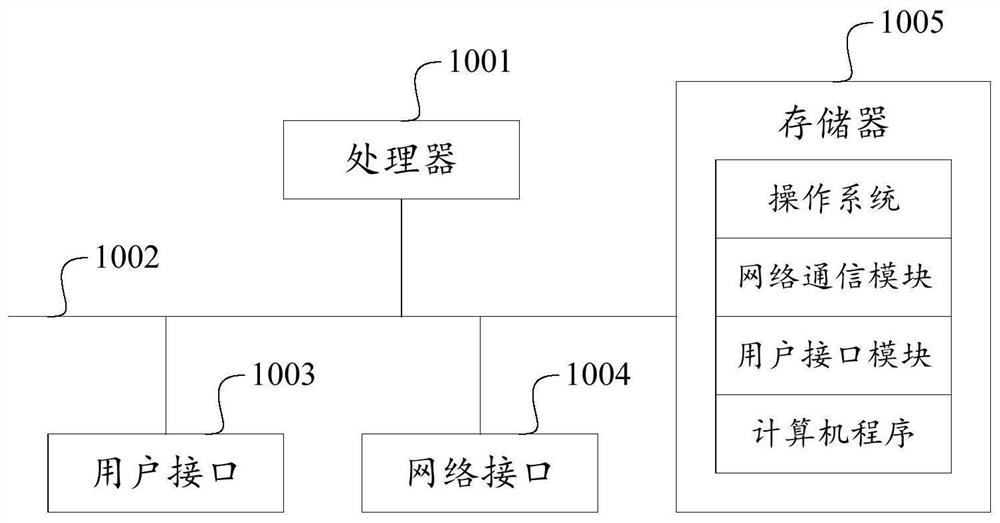
[0064] Such as figure 2 Shown is a schematic diagram of the hardware structure of the image artifact removal device. The device may include: a processor 1001 , such as a CPU (Central Processing Unit, central processing unit), a communication bus 1002 , a user interface 1003 , a network interface 1004 , and a memory 1005 .
[0065] Those skilled in the art can understand that, figure 2 The hardware structure shown in FIG. 2 does not con...
Embodiment 2
[0111] Based on the same inventive concept, refer to Figure 8 , the first embodiment of the image artifact elimination device of the present invention is proposed, the image artifact elimination device may be a virtual device, and is applied to an image artifact elimination device.
[0112] Combine below Figure 8 The schematic diagram of the functional modules shown is a detailed description of the image artifact elimination device provided in this embodiment, and the device may include:
[0113] The input module is used to obtain the input image, and the input image is a CT scan image of the geotechnical material to be tested;
[0114] a central point identification module, configured to identify the central point of the input image;
[0115] A location information acquisition module, configured to obtain the location information of each pixel in the input image based on the center point according to the center point;
[0116] A characteristic curve value acquisition modul...
Embodiment 3
[0136] Based on the same inventive concept, refer to figure 2 , is a schematic diagram of a hardware structure of an image artifact elimination device according to various embodiments of the present invention. This embodiment provides an image artifact elimination device. The device may include a processor and a memory, and a computer program is stored in the memory. When the computer program is executed by the processor, the image artifact of the present invention can be realized. All or some steps of various embodiments of the method are eliminated.
[0137] Specifically, the image artifact elimination device refers to a terminal device or network device capable of network connection, which may be a terminal device such as a mobile phone, a computer, a tablet computer, or a portable computer, or a network device such as a server or a cloud platform.
[0138] It can be understood that the device may also include a communication bus, a user interface and a network interface....
PUM
 Abstract
Description
Claims
Application Information
 - R&D
- Intellectual Property
- Life Sciences
- Materials
- Tech Scout
- Unparalleled Data Quality
- Higher Quality Content
- 60% Fewer Hallucinations
Browse by: Latest US Patents, China's latest patents, Technical Efficacy Thesaurus, Application Domain, Technology Topic, Popular Technical Reports.
© 2025 PatSnap. All rights reserved.Legal|Privacy policy|Modern Slavery Act Transparency Statement|Sitemap|About US| Contact US: help@patsnap.com