Temperature detection device based on surface plasmon
A surface plasmon and detection device technology, applied in the field of temperature detection, can solve the problems of low detection accuracy and large interference, and achieve the effects of small size, avoiding potential safety hazards and facilitating integration
- Summary
- Abstract
- Description
- Claims
- Application Information
AI Technical Summary
Problems solved by technology
Method used
Image
Examples
Embodiment 1
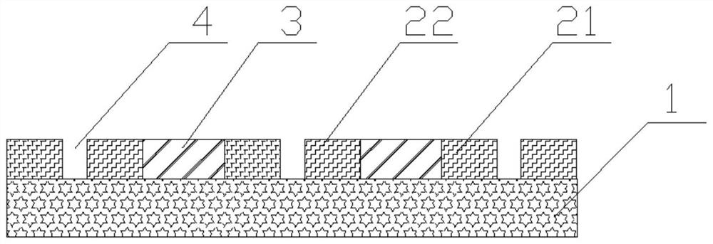
[0037] Such as figure 1 As shown, the temperature detection device based on surface plasmons includes a transparent elastic material layer 1, a metal array structure and a thermal expansion material block 3; the metal array structure is arranged on the transparent elastic material layer 1; the metal array The structure is composed of periodically arranged metal units 2, and gaps are arranged on the metal units 2; there are gaps 4 between the metal units 2 and the metal units 2; the thermal expansion material blocks 3 are arranged in the gaps.
[0038] The thermal expansion material block is made of ethylene-vinyl acetate polymer with a large thermal expansion coefficient, and the temperature change of the thermal expansion material block is proportional to the length change, so as to realize temperature detection with higher sensitivity.
[0039] The material of the transparent elastic material layer is polydimethylsiloxane, so that light can pass through the transparent elast...
Embodiment 2
[0047] Such as figure 2As shown, the temperature detection device based on surface plasmons includes a transparent elastic material layer 1, a metal array structure and a thermal expansion material block 3, and the metal array structure is arranged on the transparent elastic material layer 1; the metal array structure consists of a periodic Arranged metal units, the metal unit is provided with a through gap, the cross section of the gap is rectangular. The metal unit is divided into a first metal block 21 and a second metal block 22, and the thermal expansion material block 3 is arranged in a gap between the first metal block 21 and the second metal block 22. That is to say, the heat-expandable material block 3 is in contact with the transparent elastic material layer 1 , and the expansion of the heat-expandable material block 3 will drive the deformation of the transparent elastic material layer 1 .
[0048] Specifically, in the present invention, light is irradiated on the...
Embodiment 3
[0051] On the basis of embodiment 2, the difference between the present invention and embodiment 2 only lies in, as image 3 As shown, the notch on the metal unit of this embodiment is trapezoidal, and the notch runs through the metal unit, increasing the contact area with the first metal block 21 and the second metal block 22. In addition, the thermal expansion material block 3 received by the metal block The thrust of expansion is not uniform, the thrust received by the upper ends of the first metal block 21 and the second metal block 22 increases, the gap 4 between the first metal block 21 and the adjacent second metal block 22 becomes an inverted wedge shape, and light passes through the gap The amount transmitted is reduced. The gap is trapezoidal, and the gap 4 changes more when the temperature changes, the red shift of the spectral line is more obvious, and the accuracy of temperature detection is higher.
PUM
| Property | Measurement | Unit |
|---|---|---|
| Width | aaaaa | aaaaa |
Abstract
Description
Claims
Application Information
 - R&D
- Intellectual Property
- Life Sciences
- Materials
- Tech Scout
- Unparalleled Data Quality
- Higher Quality Content
- 60% Fewer Hallucinations
Browse by: Latest US Patents, China's latest patents, Technical Efficacy Thesaurus, Application Domain, Technology Topic, Popular Technical Reports.
© 2025 PatSnap. All rights reserved.Legal|Privacy policy|Modern Slavery Act Transparency Statement|Sitemap|About US| Contact US: help@patsnap.com


