A large bypass ratio turbofan engine core cabin ventilation structure and ventilation method

A turbofan engine with a large bypass ratio technology, which is applied in the direction of engine components, engine cooling, sustainable transportation, etc., can solve the problem that the number of bleed air openings on the wall cannot be too large, cannot be reached, and the circumferential cooling of the core cabin is not enough Uniformity and other issues to achieve good flow heat transfer effect in the cabin and good exhaust effect

Active Publication Date: 2022-07-12
NANJING UNIV OF AERONAUTICS & ASTRONAUTICS
View PDF12 Cites 0 Cited by
  • Summary
  • Abstract
  • Description
  • Claims
  • Application Information

AI Technical Summary

Problems solved by technology

Because of the consideration of the flow loss of the outer culvert, the structure must not have too many air-inducing openings on the wall, which will lead to unfavorable factors such as uneven cooling inside the core nacelle; Intake effect, which inevitably affects the intake air flow, even if the minimum cooling air volume is not reached
In order to increase the amount of air-entrainment, only the number of air-entrainment openings on the wall is increased, thereby increasing the flow loss of the outer culvert

Method used


Image

  • A large bypass ratio turbofan engine core cabin ventilation structure and ventilation method
  • A large bypass ratio turbofan engine core cabin ventilation structure and ventilation method
  • A large bypass ratio turbofan engine core cabin ventilation structure and ventilation method

Examples


Embodiment 1

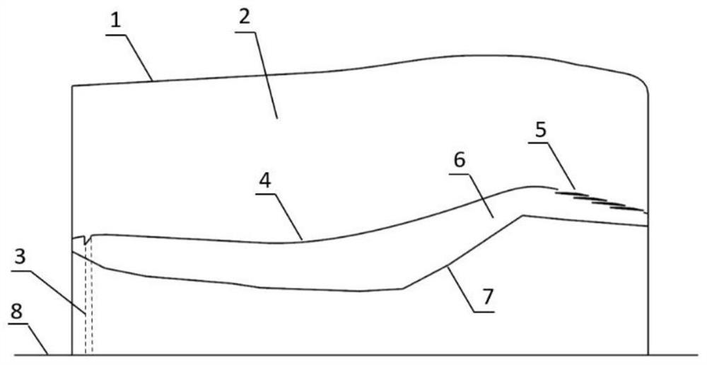
[0037] see Figure 1-Figure 10 , the present embodiment provides a high bypass ratio turbofan engine core cabin ventilation structure, including:

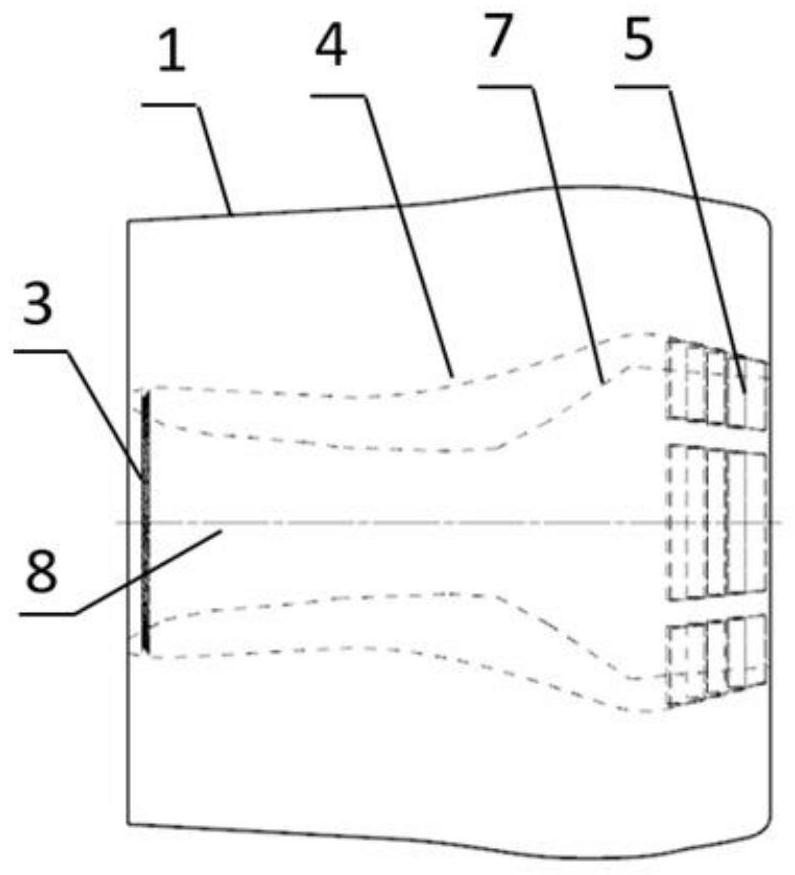
[0038] Outer bypass duct wall 1, core engine room wall 4, core engine casing 7, the outer bypass channel 2 is formed between the outer bypass wall surface 1 and the core engine room wall surface 4, and the core engine room wall 4 and the core engine casing 7 constitute the core cabin 6;

[0039] Among them, an air inlet annular cavity 3 is provided inside and upstream of the core engine room. The air intake annular cavity 3 is used to connect the external flow channel 2 and the core engine room 6, and is also provided on the wall surface 4 of the core engine room and at the rear position. An exhaust grill 5 is provided, and the exhaust grill 5 is used to discharge the cooling gas inside the core nacelle 6 into the bypass flow channel 2 .

[0040] Specifically, in this embodiment, the interior of the air intake annular cavity 3 is...

Embodiment 2

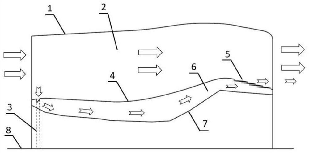
[0043] On the basis of Embodiment 1, the present embodiment provides a ventilation method for the core cabin of a turbofan engine with a large bypass ratio based on a ventilation structure for a core cabin of a turbofan engine with a large bypass ratio provided in Embodiment 1, which specifically includes:

[0044] Step 1: Using the stamping effect, the external airflow in the external runner 2 flows into the cavity of the air intake annular cavity 3 connected to the core nacelle wall 4 through the air intake holes 9 on the core nacelle wall 4;

[0045] Step 2: After the cooling air enters the inside of the air inlet annular cavity 3, it first flows in the circumferential direction, and then from the exhaust holes 11 on the end face 10 of the annular cavity of the air intake annular cavity 3, it is uniformly discharged into the circumferential direction. In the core cabin 6; because the annular cavity end face 10 of the intake annular cavity 3 has an inclined angle, the cooling...


PUM


Abstract

The invention provides a ventilation structure for a core cabin of a turbofan engine with a large bypass ratio and a ventilation method thereof, comprising an air inlet annular cavity and a set of exhaust grilles; The ram air intake effect is used to introduce the extrinsic airflow into the intake annular cavity, and the cooling airflow first flows in the circumferential direction in the cavity, and then is uniformly discharged into the core engine room through the exhaust holes on the end face of the annular cavity in the circumferential direction. In the inner area, it is used to realize that the external cooling airflow can enter the core cabin uniformly in the circumferential direction; there is an inclined angle on the end face of the annular cavity, so that the external cooling airflow flows to the fluid area in the core engine room at a certain angle, which is better to achieve. For the purpose of cooling the surface of the core machine casing, to obtain a better flow and heat exchange effect in the cabin; the exhaust grille is located on the downstream wall of the core engine room, and the air in the core engine room is drawn from the exhaust grille by the suction effect of the external airflow. Suck it out, mix with the external airflow and enter the external channel.

Description

technical field [0001] The invention relates to the technical field of engine core cabin ventilation structures, in particular to a large bypass ratio turbofan engine core cabin ventilation structure and a ventilation method thereof. Background technique [0002] The gas turbine engine core dissipates a large amount of heat during normal operation. The high-temperature gas transfers heat to the core engine room in the form of heat radiation and convection heat transfer, and the core engine exchanges heat in the form of heat conduction and heat radiation. high. The high temperature in the core cabin will cause abnormal operation or damage to the core components, which will directly affect the flight safety of the aircraft in severe cases. Therefore, considering the longevity of the accessories and structures in the core cabin, it is very important to design an appropriate core cabin ventilation and cooling system solution to provide the airflow required for core cabin cooli...

Claims


Application Information

Patent Timeline
Patent Type & Authority Patents(China)
IPC IPC(8): F02C7/18
CPCF02C7/18Y02T50/60
Inventor 单勇尹华莉刘昊邓明赵强谭晓茗张靖周
Owner NANJING UNIV OF AERONAUTICS & ASTRONAUTICS
Why Eureka
Try Eureka