
Optical system for film projection and projection equipment

An optical system and film technology, applied in optics, optical components, instruments, etc., can solve problems such as insufficient field of view and poor imaging image quality, achieve high imaging quality, and achieve the effect of large-area image coverage

Active Publication Date: 2021-11-02
SHENZHEN LINKLITE SMART LIGHTING CO LTD
View PDF6 Cites 0 Cited by
  • Summary
  • Abstract
  • Description
  • Claims
  • Application Information

AI Technical Summary

Problems solved by technology

At present, all small projection devices have the problem of insufficient field of view and poor image quality.

Method used


Image

  • Optical system for film projection and projection equipment
  • Optical system for film projection and projection equipment
  • Optical system for film projection and projection equipment

Examples


Embodiment Construction

[0027] The present invention will be further described below with reference to the accompanying drawings and in combination with preferred embodiments. It should be noted that, in the case of no conflict, the embodiments in the present application and the features in the embodiments can be combined with each other. In order to facilitate readers' understanding and to keep the drawings concise, certain components in the drawings of the present invention are not drawn according to actual scale, and cannot be used to limit the scope of the present invention.

[0028] Although the present invention uses terms such as first, second, third, etc. to describe various elements, it should be understood that these elements should not be limited by such terms, which are only used to distinguish certain elements An element with another element, by itself, does not imply any preceding ordinal number of the element, nor does it imply an arrangement order of one element with another element, ...


PUM


Abstract

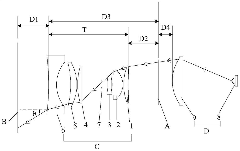
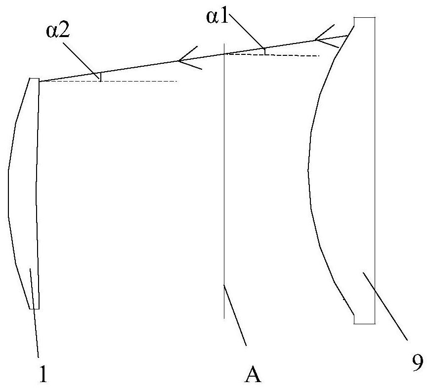
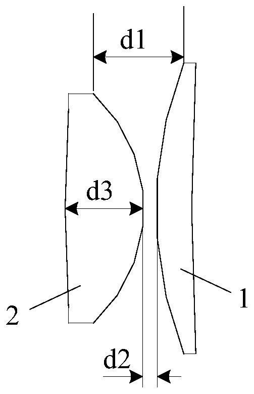
The invention discloses an optical system for film projection and projection equipment. The optical system comprises a film, an illumination system and a projection objective lens, the projection objective lens comprises a first lens, a second lens, a third lens, an aperture diaphragm, a fourth lens, a fifth lens and a sixth lens which are sequentially arranged along the same optical axis from a film side to an imaging side, the first lens, the second lens, the fourth lens and the fifth lens are positive lenses, and the third lens and the sixth lens are negative lenses; the F number of the projection objective lens is in a range of 3-6; the illumination system comprises a light source and a lens group, light emitted by the light source passes through the lens group and then enters a film in the form of collimated light or convergent light forming an angle of less than or equal to 10 degrees with a horizontal line, and the light entering a first lens after passing through the film is parallel to an optical axis or converges towards the optical axis at an angle of less than or equal to 10 degrees with the horizontal line; and finally imaging is performed on an imaging target surface through the projection objective lens. The optical system has the advantages of high imaging quality, low distortion, large projection area and the like.

Description

technical field [0001] The invention relates to the field of projection imaging, in particular to an optical system and projection equipment for film projection. Background technique [0002] As projection equipment is more and more used in people's work and life, the requirements for projection equipment, such as imaging quality, distortion, and projection area, are also getting higher and higher. At present, small projection devices have the problems of insufficient field of view and poor image quality. The optical system is the core component of the projection device. How to improve the projection imaging quality of the projection objective lens, reduce the distortion value, and increase the projection area are issues of concern in this field. Especially for replaceable film-type home projection equipment, the requirements for ultra-wide field of view and image quality have become the trend of consumer demand. Contents of the invention [0003] The object of the prese...

Claims


Application Information

Patent Timeline
Patent Type & Authority Applications(China)
IPC IPC(8): G02B13/06G02B13/00G03B21/14G03B21/20
CPCG02B13/16G02B13/06G02B13/00G03B21/14G03B21/208
Inventor 张尚超
Owner SHENZHEN LINKLITE SMART LIGHTING CO LTD
Learn More