
Double suction pump capable of preventing water accumulation in groove

A technology for double-suction pumps and water storage tanks, which is applied to non-volume pumps, pumps, components of pumping devices for elastic fluids, etc., and can solve the problem of reducing the service life of double-suction pumps, damage to parts, and grooves in double-suction pumps Problems such as stagnant water

Pending Publication Date: 2021-11-02
ESKE PUMP
View PDF5 Cites 1 Cited by
  • Summary
  • Abstract
  • Description
  • Claims
  • Application Information

AI Technical Summary

Problems solved by technology

[0003] The existing double-suction pump will vibrate during operation, causing damage to its internal parts. After the work is completed, there will often be a problem of water accumulation in a large number of grooves inside the double-suction pump, which will greatly reduce the service life of the double-suction pump.

Method used


Image

  • Double suction pump capable of preventing water accumulation in groove
  • Double suction pump capable of preventing water accumulation in groove
  • Double suction pump capable of preventing water accumulation in groove

Examples


Embodiment 1

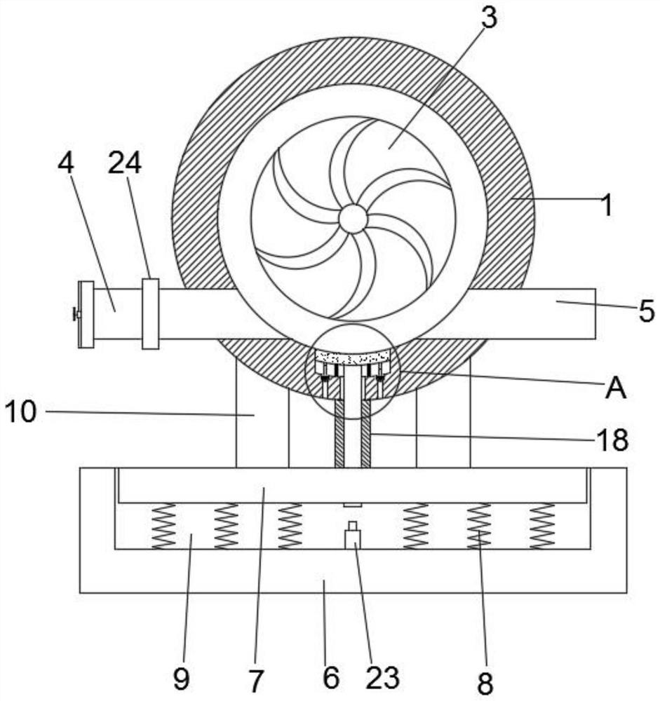
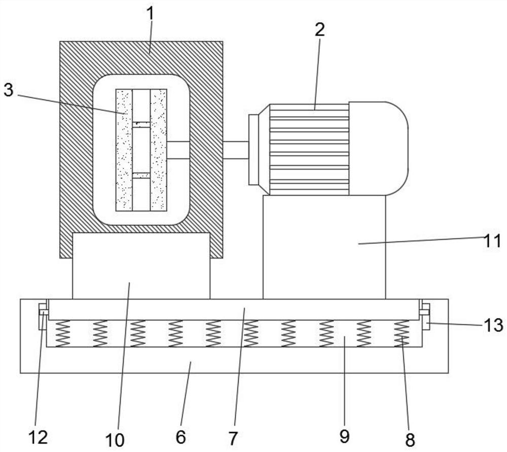
[0027] Such as Figure 1-4 As shown, a double-suction pump for preventing ponding in grooves includes a pump casing 1 and a motor 2, the pump body 1 is provided with an impeller 3 inside, and the output shaft of the motor 2 runs through the pump casing 1 and is fixedly connected to the impeller 3 The two sides of the pump casing 1 are respectively provided with a water inlet pipe 4 and a drain pipe 5. The motor 2 drives the impeller 3 to rotate counterclockwise. ;

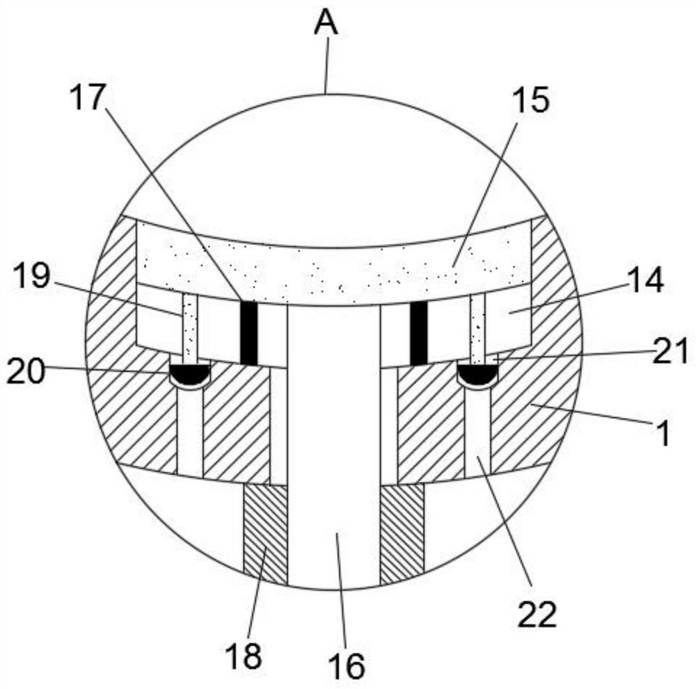
[0028] The bottom side of the inner wall of the pump casing 1 is provided with a water tank 14, and a partition 15 is movably connected in the water tank 14, and a guide rod 16 is installed at the bottom of the partition 15, and the bottom end of the guide rod 16 penetrates and extends to On the outside of the pump casing 1, the bottom end of the guide rod 16 penetrates and extends to the lower side of the buffer plate 7. An electric push rod 23 is fixedly installed in the buffer tank 9, and the telescopic end of ...

Embodiment 2

[0039] On the basis of Example 1, such as Figure 5-8 As shown; the filter screen 32 is fixedly connected to one end of the straight rod 29 away from the side of the impeller 3, and the other end of the straight rod 29 is fixedly installed with a mounting block 33, and the outside of the mounting block 33 is fixedly mounted with several groups of connecting bars 27, The connecting bar 27 is arranged in a ring around the center of the mounting block 33, and a sleeve 28 is fixedly installed on one side of the connecting bar 27 near the filter screen 32. The inside of the sleeve 28 is provided with a built-in screw thread, and the outside of the water inlet pipe 4 is provided with There are external threads, and the sleeve 28 is connected to the water inlet pipe 4 through threads. The water inlet pipe 4 is fixedly installed with a fixing plate 31 inside, and the filter screen 32 abuts against the fixing plate 31 .

[0040] Specifically, the filter screen 32 needs to be installed ...


PUM


Abstract

The invention relates to the technical field of double suction pumps, and discloses a double suction pump capable of preventing water accumulation in a groove. The double suction pump comprises a pump shell and a motor, an impeller is arranged in the pump body, an output shaft of the motor penetrates through the pump shell and is fixedly connected with the impeller, and a water inlet pipe and a water outlet pipe penetrate through the two sides of the pump shell correspondingly. A water accumulation groove is formed in the bottom side of the inner wall of the pump shell, a partition plate is movably connected into the water accumulation groove, a guide rod is installed at the bottom of the partition plate, the bottom end of the guide rod penetrates through and extends to the outer side of the pump shell, a connecting rod is fixedly installed on the bottom side of the partition plate, and a sealing plug is fixedly connected to the bottom end of the connecting rod. A drainage groove is formed in the bottom of the water accumulation groove, a water outlet groove is formed in the bottom of the drainage groove, the bottom of the water outlet groove penetrates through the pump shell, and the sealing plug is in interference connection with the drainage groove. A damping device is arranged at the bottom of the pump shell and plays a role in damping and energy absorption, and meanwhile accumulated water left in the pump shell can be effectively cleaned out.

Description

Technical field: [0001] The invention relates to the technical field of double-suction pumps, in particular to a double-suction pump for preventing water accumulation in grooves. Background technique: [0002] As an important form of centrifugal pump, double-suction pump is widely used in engineering because of its high lift and large flow. The impeller of this type of pump is actually composed of two back-to-back impellers, and the water flow from the impeller is merged into a volute. The double-suction pump has the following characteristics: it is equivalent to two single-suction impellers of the same diameter working at the same time, and the flow rate can be doubled under the same outer diameter of the impeller; the pump casing is opened horizontally, which is convenient for inspection and maintenance. The inlet and outlet of the suction pump are in the same direction and perpendicular to the pump shaft, which is convenient for the arrangement and installation of the pu...

Claims


Application Information

Patent Timeline
Patent Type & Authority Applications(China)
IPC IPC(8): F04D1/00F04D13/06F04D29/42F04D29/66F04D29/70F04D29/08F04D29/00
CPCF04D1/006F04D13/06F04D29/426F04D29/668F04D29/708F04D29/086F04D29/007
Inventor 曲昌平曹珠明孙才军
Owner ESKE PUMP
Learn More