
Boundary control device for radioactive contamination isolation area of nuclear power plant

A technology for border control and isolation area, applied in the direction of fences, roads, road signs, etc., it can solve the problems of unguaranteed border integrity, human body contamination and pollution of non-working group members, and achieves good impact resistance and radiation defense performance, The effect of reducing the risk of site contamination and reducing the dose of radiation exposure

Pending Publication Date: 2021-11-02
上海勋迈科技有限公司
View PDF0 Cites 0 Cited by
  • Summary
  • Abstract
  • Description
  • Claims
  • Application Information

AI Technical Summary

Problems solved by technology

[0003] (1) The stability of isolation piles is low, the boundary integrity cannot be guaranteed, and radioactive pollution is easy to spread and cause site pollution;
[0004] (2) There is no rigid entity on the boundary, and there is a risk of human contamination when non-working group members perform other work in the adjacent area;
[0005] (3) The dose of the disassembled equipment is too high during on-site storage, which has a great impact on the environmental dose rate of the surrounding area, which may cause unnecessary dose exposure to non-staff personnel, which does not comply with the ALARA principle

Method used


Image

  • Boundary control device for radioactive contamination isolation area of nuclear power plant
  • Boundary control device for radioactive contamination isolation area of nuclear power plant
  • Boundary control device for radioactive contamination isolation area of nuclear power plant

Examples


Embodiment Construction

[0030] The present invention will be further described in detail below in conjunction with the embodiments and the accompanying drawings, but the embodiments of the present invention are not limited thereto.

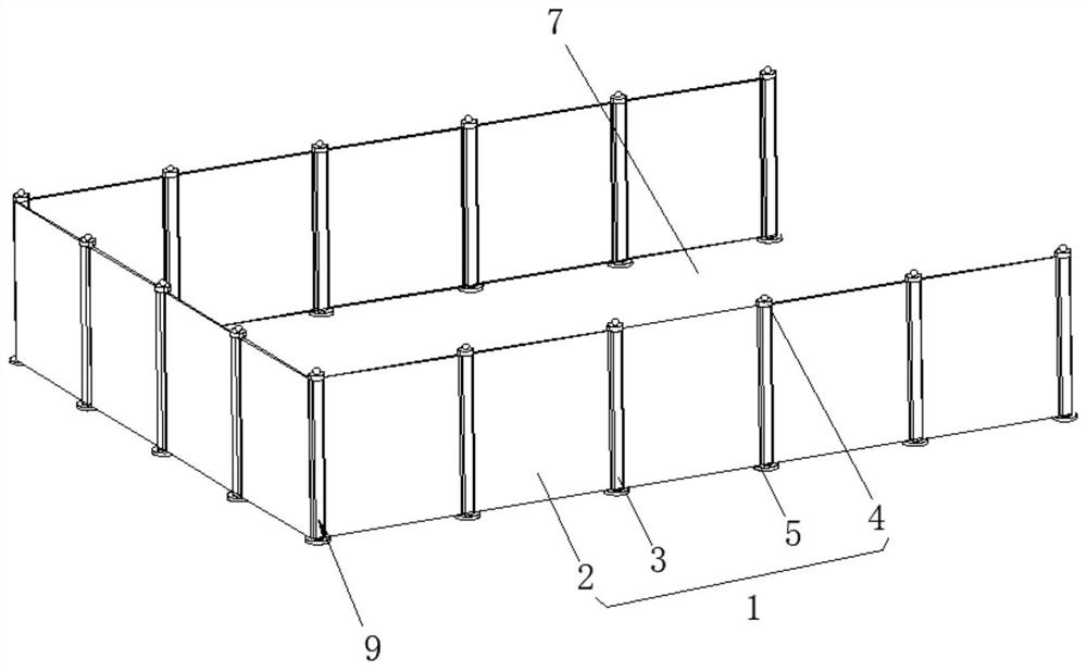
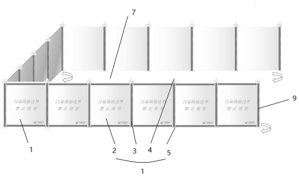
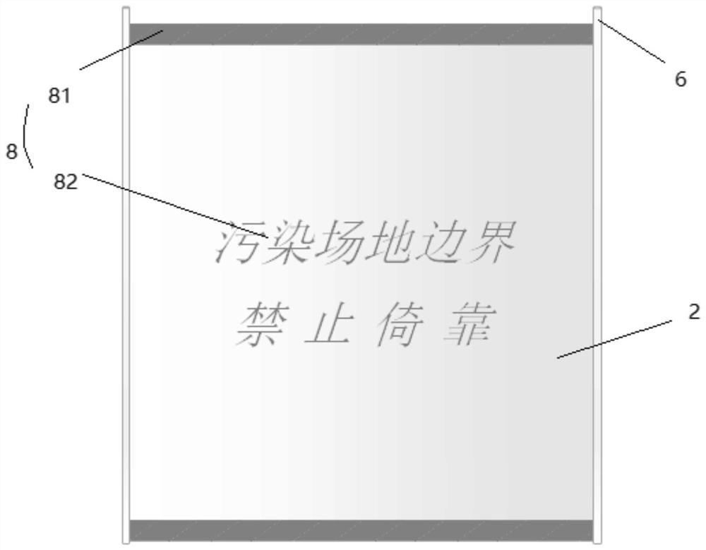
[0031] to combine Figure 1 to Figure 6 , a boundary control device for the radioactive pollution isolation area of ​​a nuclear power plant, which can be applied to other sites that need to isolate radioactive contamination other than nuclear power plants. This embodiment uses a nuclear power plant as an example. When the opening equipment of the circuit pipeline is dismantled, in order to avoid the safety accident caused by the spread of radioactive loose pollution, the radioactive pollution isolation area 7 for surrounding the dismantled equipment is built through this kind of boundary control device.

[0032] In conventional pollution isolation areas, warning tapes and isolation piles are often used as boundaries, and warning tapes are set on the upper ends between tw...


PUM


Abstract

The invention relates to a boundary control device for a radioactive contamination isolation area of a nuclear power plant, and belongs to the technical field of radioactive contamination protection. The boundary control device comprises a plurality of isolation assemblies, wherein the isolation assemblies are detachably and fixedly connected, the boundary control device is of a seamlessly-arranged solid structure as a whole, and the total length of the boundary control device is adjusted according to the number of the isolation assemblies; the included angle formed between every two adjacent isolation assemblies can be rotationally adjusted by 360 degrees, and warning mark assemblies are formed on the isolation assemblies; the radioactive contamination isolation area which is used for surrounding disassembly equipment is formed among the plurality of isolation assemblies in a matched mode, and the boundary control device has the functions of building the radioactive contamination isolation area and controlling the boundary of the radioactive contamination isolation area and has an external warning effect; and in addition, the boundary of the radioactive contamination isolation area can be effectively controlled, the site contamination risk is effectively reduced, the contamination risk of workers is reduced, and the exposure dose of the workers in the surrounding area is reduced.

Description

technical field [0001] The invention relates to the technical field of radioactive pollution protection, in particular to a boundary control device for a radioactive pollution isolated area of ​​a nuclear power plant. Background technique [0002] Nuclear power plants usually need to dismantle the primary circuit pipeline opening equipment during equipment maintenance and overhaul. In order to avoid the spread of radioactive loose pollution, it is necessary to build a radioactive pollution isolation area. Conventional pollution isolation areas are usually bounded by warning tapes and isolation piles, so there are the following problems in the working process: [0003] (1) The stability of isolation piles is low, the boundary integrity cannot be guaranteed, and radioactive pollution is easy to spread and cause site pollution; [0004] (2) There is no rigid entity on the boundary, and there is a risk of human contamination when non-working group members perform other work in ...

Claims


Application Information

Patent Timeline
Patent Type & Authority Applications(China)
IPC IPC(8): E04H17/16E04H17/20E04H17/22E01F9/615E01F9/669
CPCE04H17/16E04H17/20E04H17/22E01F9/615E01F9/669
Inventor 曲全斌陈睿叶沥施维泽胡颜
Owner 上海勋迈科技有限公司
Learn More