
Mechanical automatic feeding device and feeding method thereof

An automatic feeding, mechanical technology, applied in metal processing and other directions, can solve the problems of assembly difficulty, complex structure, collision, etc., and achieve the effect of reducing assembly difficulty, simplifying equipment structure, and running smoothly.

Pending Publication Date: 2021-11-02
东莞朗硕自动化科技有限公司
View PDF8 Cites 2 Cited by
  • Summary
  • Abstract
  • Description
  • Claims
  • Application Information

AI Technical Summary

Problems solved by technology

There are mainly two ways to realize the feeding of the bar. The traditional way is manual feeding. This method requires workers to push the bar towards the direction of the CNC machine tool, which is extremely time-consuming and laborious, and is likely to cause safety hazards; and due to the existence of different people The difference, the feeding can not meet the uniform standard
[0003] The current method is the mechanical automatic feeding method, which mostly needs to be implemented by manipulators, and has the disadvantages of complex structure, difficult assembly and high cost, and the processing of bars often leaves residual materials, and conventional mechanical equipment does not carry out timely processing of the residual materials. Processing will affect the quality of the subsequent feeding, and even cause collision with the next bar to be sent because the residual material remains, resulting in the problem of coiling
[0004] In view of the above-mentioned related technologies, the implementation quality of material feeding needs to be improved urgently

Method used


Image

  • Mechanical automatic feeding device and feeding method thereof
  • Mechanical automatic feeding device and feeding method thereof
  • Mechanical automatic feeding device and feeding method thereof

Examples


Embodiment Construction

[0081] The following is attached Figure 1-13 The application is described in further detail.

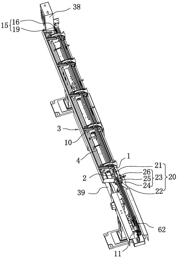
[0082] refer to figure 1 , a mechanical automatic feeding device, comprising:

[0083] The stock trough 1 is used as a conveying channel for rods, and one end of the stock trough 1 is connected with a residual material collection trough 2 . The bottom of the residual material collection tank 2 communicates with a storage box 39 to increase the amount of residual material that can be accommodated.

[0084] The feeding mechanism 3 is used to transfer the rods to the feeding tank 1.

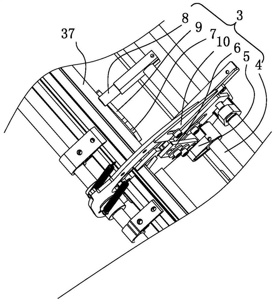
[0085] As one implementation, see figure 1 and figure 2 , the feed mechanism 3 includes a support bracket 10, a feed rotating rod 4, a feed dial 5, a feed push block 6, a feed top block 7 and a feed rotary top piece 8, and the feed top block 7 is provided with a feeding Material missing corner 9, feeding top block 7 is arranged on the discharge end of the support bracket 10, the discharge end of th...


PUM


Abstract

The invention relates to the technical field of numerical control feeding equipment, in particular to a mechanical automatic feeding device and a feeding method thereof. The mechanical automatic feeding device comprises a material containing groove, a feeding mechanism, a clamping mechanism, a first driving assembly, a grabbing mechanism, a second driving assembly and a controller, wherein the material containing groove communicates with a residual material collecting groove; the clamping mechanism comprises a touch piece, a push rod and a chuck; and the grabbing mechanism comprises a sensor. The mechanical automatic feeding device has the beneficial effects that on the basis that the unified feeding standard is met through mechanical feeding, the equipment structure is simplified, the assembly difficulty is reduced, a mechanical arm is not needed, and the cost is reduced; the mechanical automatic feeding device has the function of automatically collecting residual materials, the residual materials are prevented from influencing the follow-up bar feeding effect, and the automation degree is high; and the mechanical automatic feeding device has the function of alarming and shutdown after automatically judging that abnormal conditions occur, and is stable in operation and high in safety.

Description

technical field [0001] The application relates to the technical field of numerical control feeding equipment, in particular to a mechanical automatic feeding device and a feeding method thereof. Background technique [0002] Industrial production often involves the process of using CNC machine tools to process bars, and there is a need to transport bars to CNC machine tools during the processing process. There are mainly two ways to realize the feeding of the bar. The traditional way is manual feeding. This method requires workers to push the bar towards the direction of the CNC machine tool, which is extremely time-consuming and laborious, and is likely to cause safety hazards; and due to the existence of different people The difference, the feeding can not meet the uniform standard. [0003] The current method is the mechanical automatic feeding method, which mostly needs to be implemented by manipulators, which has the disadvantages of complex structure, difficult assemb...

Claims


Application Information

Patent Timeline
IPC IPC(8): B23Q7/00B23Q7/04
CPCB23Q7/00B23Q7/008B23Q7/04
Inventor 戴志鑫戴维何伟强林华黎军
Owner 东莞朗硕自动化科技有限公司
Learn More