
Terminal laminating machine

A laminating machine and terminal technology, applied in the direction of electrical components, circuits, connections, etc., can solve the problems of prone to errors, influence on the success rate of finished product inspection, low degree of automation, etc., and achieve the effect of improving production efficiency

Pending Publication Date: 2021-10-29
东莞市彩历上自动化设备科技有限公司
View PDF0 Cites 0 Cited by
  • Summary
  • Abstract
  • Description
  • Claims
  • Application Information

AI Technical Summary

Problems solved by technology

[0002] At present, in the manufacturing equipment of server terminals, the process is relatively simple. The metal sheet and the terminal body cut out from the strip by other equipment mechanisms are received, and they are formed by riveting and pressing. A lot of equipment is required, and the materials need to be manually moved. The degree of automation is low, and the formed terminals also need to check the riveting condition manually with the naked eye, and remove the terminals with poor riveting quality. Because the naked eye detection is prone to errors, the detection success rate of the finished product is affected

Method used


Image

  • Terminal laminating machine
  • Terminal laminating machine
  • Terminal laminating machine

Examples


Embodiment Construction

[0047] The technical solutions of the present invention will be further described below in conjunction with the accompanying drawings and through specific implementation methods.

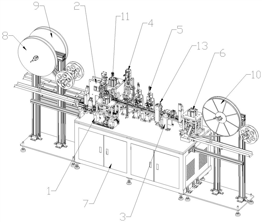
[0048] Such as figure 1 As shown, in this embodiment, a terminal bonding machine includes an equipment frame 7, a metal sheet punching mechanism 1, a synchronous feeding mechanism 2, a terminal conveying mechanism 3, a heat riveting mechanism 4, a detection mechanism 5 and Terminal body punching mechanism 6 .

[0049] A sheet metal feeding tray 8 and a terminal body feeding tray 9 are provided at the front end of the equipment rack 7 , and a sheet metal receiving tray 10 is provided at the rear end of the equipment rack 7 .

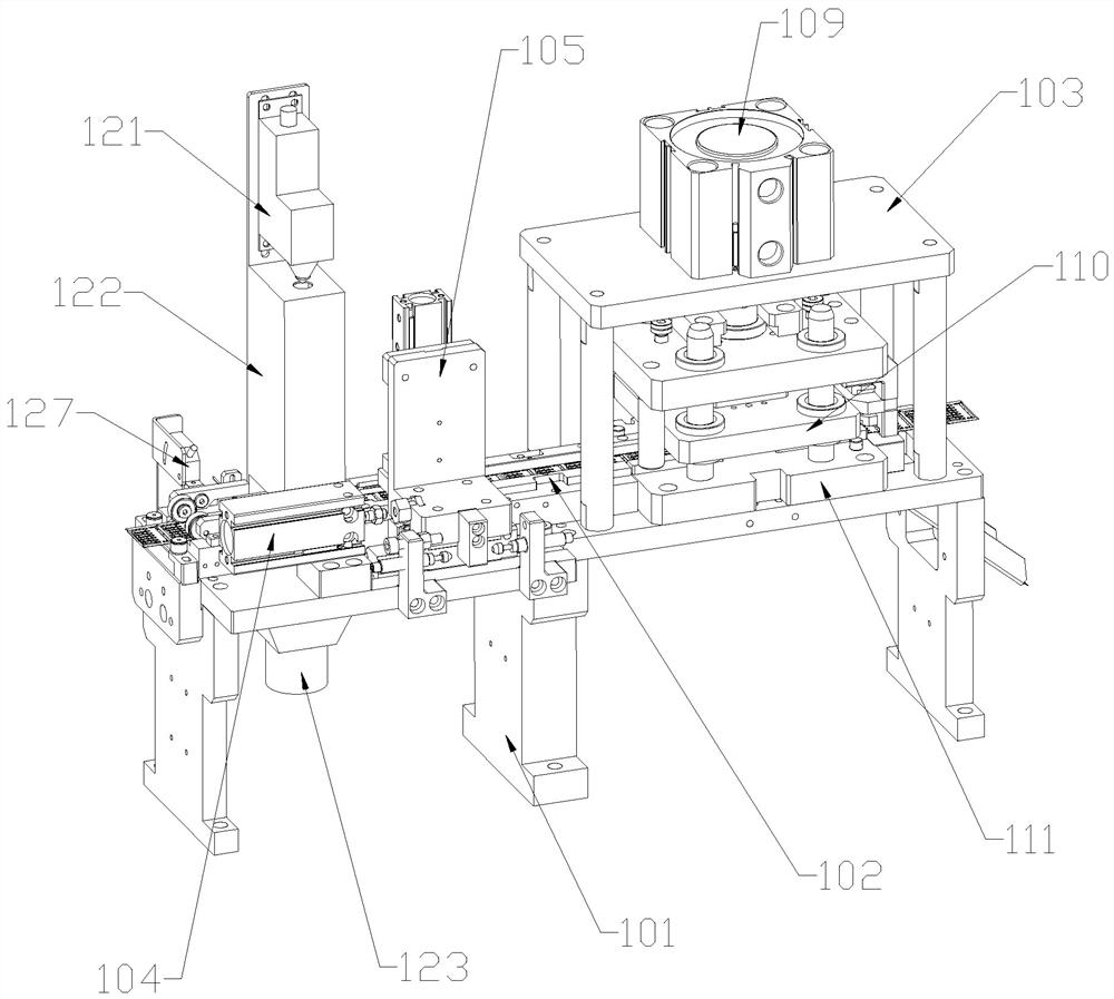
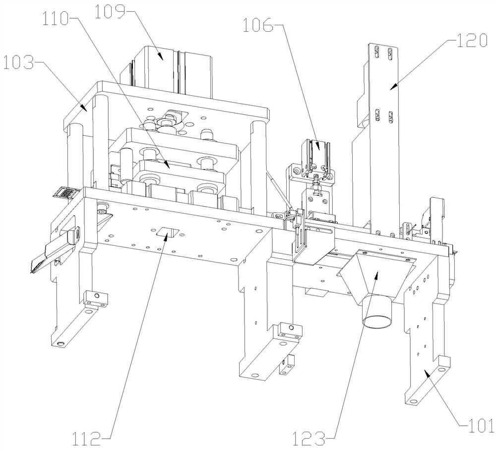
[0050] Such as Figure 2 to Figure 7 As shown, the sheet metal punching mechanism 1 includes a sheet metal conveying frame 101, a sheet metal conveying track 102 and a sheet metal punching frame 103, the sheet metal conveying track 102 is located on the sheet metal conveying ...


PUM


Abstract

The invention discloses a terminal laminating machine which comprises an equipment rack, a metal sheet punching mechanism, a synchronous taking and feeding mechanism, a terminal conveying mechanism, a hot riveting mechanism, a detection mechanism and a terminal body punching mechanism. The terminal laminating machine is used for laminating and forming a terminal body and a metal sheet, a moving needle penetrates through hole sites in the two sides of a terminal material belt for pulling, the forward moving distance and position of the terminal material belt are guaranteed, riveting and hot pressing are combined in the equipment, and the metal sheet and the terminal body are formed in time. The terminal laminating machine has a product detection function after terminal forming, the whole process is automatic, manual intervention in production is not needed, front and rear ends are automatically rolled and cut, and the production efficiency is improved.

Description

technical field [0001] The invention relates to the technical field of assembly equipment, in particular to a terminal bonding machine. Background technique [0002] At present, in the manufacturing equipment of server terminals, the process is relatively simple. The metal sheet and the terminal body cut out from the strip by other equipment mechanisms are received, and they are formed by riveting and pressing. A lot of equipment is required, and the materials need to be manually moved. The degree of automation is low, and the formed terminals also need to check the riveting condition manually by naked eyes, and remove the terminals with poor riveting quality. Because the visual inspection is prone to errors, the detection success rate of the finished product is affected. Contents of the invention [0003] An object of the present invention is to provide a terminal bonding machine to solve the problems in the prior art. [0004] For reaching this purpose, the present inve...

Claims


Application Information

Patent Timeline
Patent Type & Authority Applications(China)
IPC IPC(8): H01R43/055
CPCH01R43/055Y02E60/10
Inventor 范国民李小林
Owner 东莞市彩历上自动化设备科技有限公司
Learn More